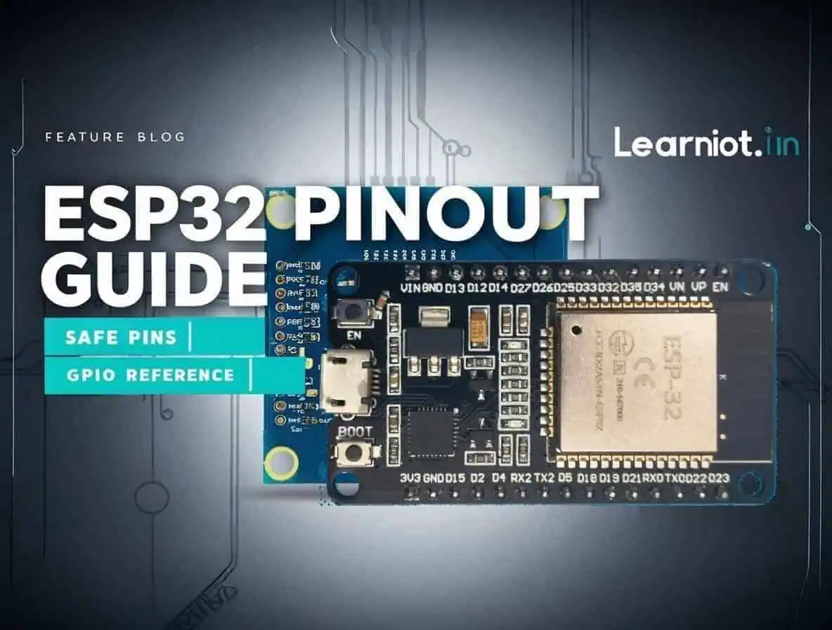
ESP32 Pinout Reference: GPIO, ADC & Safe Pins Guide
ESP32 Pinout Guide: Avoid Common Mistakes with GPIO Pins
Download ESP32 Pinout Cheat Sheet (High Resolution)
Video Overview: Your Guide to ESP32
Watch this comprehensive overview to understand ESP32 GPIO pinout, safe pins vs. strapping pins, and key features like ADC/DAC capabilities. This video covers the essential concepts—after watching, use the table of contents below to jump directly to specific pin configurations, detailed specifications, or troubleshooting sections for your project needs.
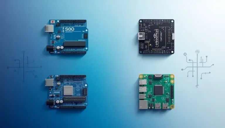
ESP32 Board Confusion: DevKit V1 vs. WROOM-32 vs. NodeMCU
I remember my first purchase. I saw listings for “NodeMCU,” “DevKit,” and “WROOM,” and I felt completely confused about which one matched my tutorial.
Think of it like a car: ESP-WROOM-32 is the engine (the chip). ESP32 DevKit V1 is the car body (the board you plug in). NodeMCU is a brand/style of car that looks very similar, so people often use the names interchangeably.
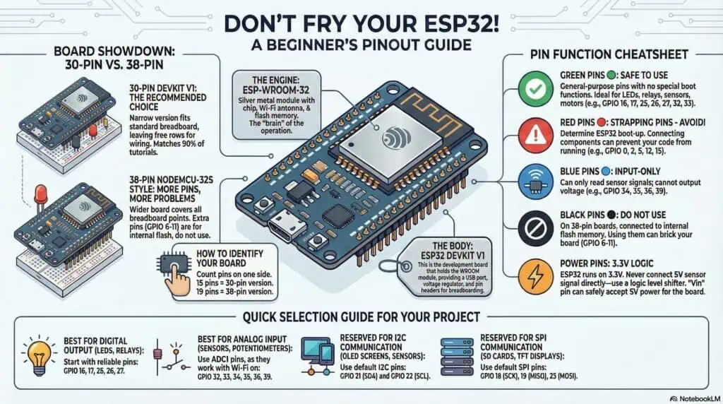
30-Pin ESP32 DevKit V1
📌 BEGINNER-FRIENDLY PIN GUIDE:
🟢 SAFE PINS (Start with these):
• GPIO16 (RX2), GPIO17 (TX2) → LEDs, Relays, Motors ← ADD THIS
• GPIO13, GPIO14, GPIO25, GPIO26, GPIO27 → LEDs, Relays, Motors
• GPIO32, GPIO33 → Analog Sensors (ADC)
• GPIO21 (SDA), GPIO22 (SCL) → I2C Devices
• GPIO18 (SCK), GPIO19 (MISO), GPIO23 (MOSI) → SPI Devices
⚠️ STRAPPING PINS (Avoid for beginners):
• GPIO0, GPIO2, GPIO5, GPIO12, GPIO15 → Cause boot issues
🔵 INPUT-ONLY PINS (Sensors only, no LEDs):
• GPIO34, GPIO35, GPIO36, GPIO39 → Can’t output voltage
💡 PRO TIP: If you see multiple labels on a pin (like “Touch8 | ADC2_5 | GPIO33”),
you can use ANY of those functions on that pin. GPIO33 works for touch sensing,
analog reading, OR simple digital input/output.
38-Pin NodeMCU-32S Style
- 🟩 = Safe GPIO
- 🔴 = Strapping pin (CAUTION: boot issues)
- 🟦 = Input-only (NO output, sensors only)
- ⚫ = Not usable (flash memory pins—DO NOT CONNECT)
- 3V3, VIN, GND, EN = Power & control
The Engine: ESP-WROOM-32
This is the silver metal square you see soldered onto the board. It contains the brain (the chip), the Wi-Fi antenna, and the flash memory. The common beginner mistake is buying this bare module because it’s cheaper, then realizing it cannot plug into a breadboard and needs extra circuitry to be usable.
The Car Body: ESP32 DevKit V1
This is the black development board that holds the WROOM module and gives you:
- USB port for programming
- Voltage regulator for 3.3V
- Pin headers that fit on a breadboard
Most ESP32 pinout diagrams on hobby blogs are actually showing this DevKit-style board.
The Brand Style: NodeMCU (ESP32)
“NodeMCU” started as a popular ESP8266 board and name.
Manufacturers reused the name for ESP32 boards (like “NodeMCU-32S”) because makers already trusted it.
In practice, these boards behave almost the same as a DevKit V1; the main differences are layout, width, and sometimes minor pin labeling changes.
Case Study: The “Wrong Board” Confusion
A student once showed me a NodeMCU-32 board and asked, “Your tutorial is for DevKit V1, so this won’t work, right?”
We selected “DOIT ESP32 DevKit V1” in the Arduino IDE anyway, hit upload, and the code ran perfectly.
Why it worked: The only differences were the logo and silkscreen text. The ESP32 pinout and GPIO numbers the code cared about were identical.
Key lesson: If your board says “ESP32” or “ESP-WROOM-32” on the module, select “ESP32 DevKit V1” in Arduino IDE regardless of the brand name printed on the board.
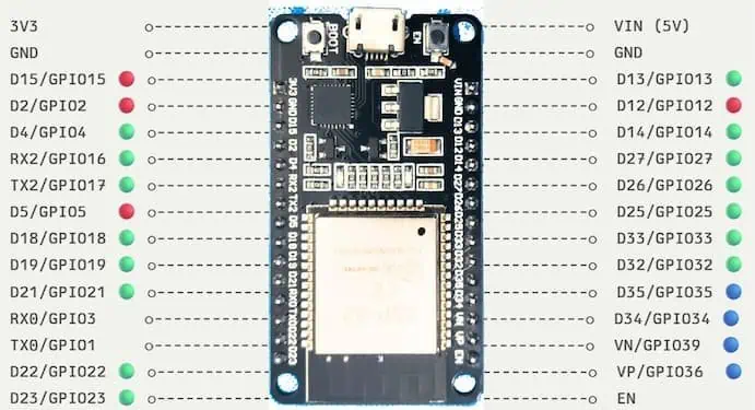
ESP32 Pinout Diagram (30-Pin vs. 38-Pin Version)
The first time I opened a tutorial that showed a different number of pins than my board, I thought there was a mistake with my order.
There was no mistake. ESP32 development boards simply come in two main pin configurations, and following the wrong pinout diagram is a fast way to connect power where ground should be.
The 30-Pin Version (DevKit V1)
This is the most common version sold on Amazon, AliExpress, and hobby electronics stores.
It is narrow enough to fit on a standard breadboard with one row of holes left open on each side, which means you can actually plug in your jumper wires without running them under the board.
When most ESP32 tutorials say “use GPIO 25,” they are assuming you have this 30-pin version in front of you.
The 38-Pin Version (NodeMCU-32S Style)
This version exposes eight extra pins compared to the 30-pin board.
Sounds great, right? Not really. Six of those extra pins are GPIO 6 through GPIO 11, which are internally connected to the flash memory chip, and using them will brick your board or cause unpredictable crashes.
The other two extra pins are usually just one more GND (ground) and GPIO 0 (the boot pin).
The Breadboard Problem
Here is the frustrating part: the 38-pin board is too wide for a single breadboard.
If you plug it into the center channel of a standard breadboard, it covers all the connection points on both sides, leaving zero space to wire anything.
The workaround I use is placing two breadboards side by side and straddling the ESP32 across the gap like a bridge. It works, but it looks messy and wastes desk space.
Which One Should You Buy?
Unless you have a very specific need for the extra ground pin or you are designing custom hardware, stick with the 30-pin version.
It fits breadboards cleanly, matches 90 percent of online tutorials, and costs about the same price.
The 38-pin version is not “better” just because it has more pins; most of those pins are unusable, anyway.
How to Identify Your Board
Before you start wiring, physically count the pins on one side of your board.
If you count 15 pins on the left side, you have the 30-pin version. If you count 19 pins, you have the 38-pin version.
Always trust the GPIO number printed next to the pin on your actual board, not the position shown in a random diagram online.
ESP-WROOM-32 Pin Definitions and Peripherals
Now that we understand which physical board we have, let me walk through the actual pins and what they do.
This is where beginners make the most mistakes, because not all pins are equal. Some will work perfectly for an LED, but connecting a relay to them will prevent your board from booting.
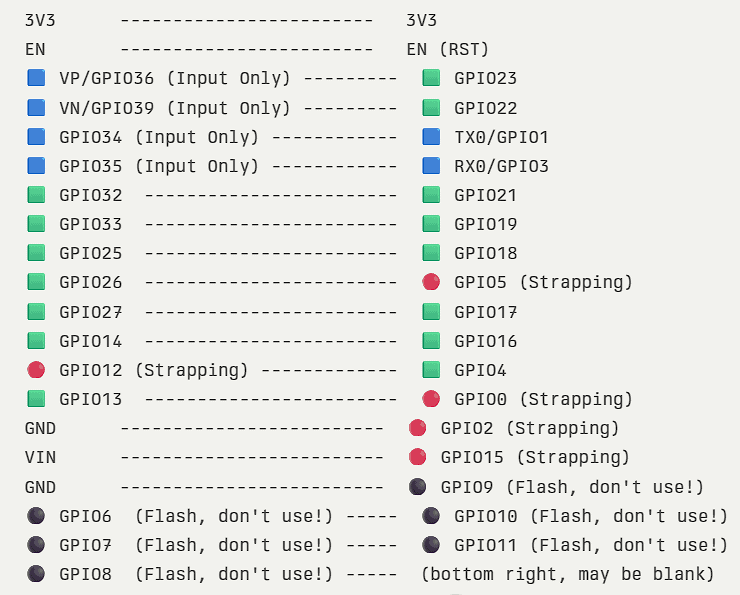
Power, Enable Pin & Ground (Vin, 3.3V, GND)
The ESP32 runs on 3.3V internally, which means the chip itself cannot tolerate 5V directly on its pins.
The Vin pin (sometimes labeled 5V) is designed to accept external power between 5V and 9V because there is a voltage regulator on the board that steps it down to 3.3V safely.
That 3.3V pin supplies regulated power from the onboard converter—it’s an output, not an input. You can power external sensors from this pin, but never connect a 5V power supply to it or the chip will be destroyed instantly.
The EN pin (Enable) is essentially the reset button. It is pulled HIGH by default, and if you connect it to Ground, the ESP32 resets.
You will see multiple GND pins scattered across the board. They are all connected internally, so it does not matter which one you use for grounding your circuits.
GPIO Pins (General Purpose Input/Output)
The ESP-WROOM-32 gives you 34 programmable pins you can set as inputs (for sensors) or outputs (for controlling devices).
Most of them support internal pull-up or pull-down resistors, which means you can connect a button directly without adding external resistors.
GPIOs 34, 35, 36, and 39 are different—they can only read signals, not send them. They cannot output voltage, and they do not have internal pull resistors, so if you connect a button to them, you must add an external pull-down resistor or the reading will float randomly.
I learned this the hard way when I tried using GPIO 36 to control an LED. The code compiled fine, but the LED never turned on because that pin physically cannot output voltage.
ADC Pins (Analog to Digital Converter)
The ESP32 has 18 ADC channels split across two blocks: ADC1 (8 channels) and ADC2 (10 channels).
You can configure the resolution up to 12 bits, allowing values from 0 to 4095 instead of Arduino’s 0 to 1023, for much finer control when reading analog sensors like potentiometers or temperature sensors.
ADC1 channels are on GPIOs 32, 33, 34, 35, 36, and 39. These are the safe ones.
ADC2 channels include GPIOs 0, 2, 4, 12, 13, 14, 15, 25, 26, and 27. A critical limitation is that you cannot use ADC2 when Wi-Fi is active.
DAC Pins and Touch Pins
The ESP32 has two true Digital to Analog Converter pins: GPIO 25 and GPIO 26.
These can output actual analog voltage (not just simulated PWM), which is useful for generating audio waveforms or controlling analog circuits that need smooth voltage changes.
The ESP32 also has 10 capacitive touch-sensing pins (T0 through T9) mapped to GPIOs 0, 2, 4, 12, 13, 14, 15, 27, 32, and 33.
You can literally connect a bare wire to one of these pins, and when you touch the wire with your finger, the ESP32 detects the change in capacitance. I have used this to create hidden touch buttons behind plastic enclosures where drilling holes for physical buttons would ruin the design.
PWM Pins and Pulse Width Modulation
Here is the beauty of the ESP32: almost any GPIO pin can generate PWM signals.
The ESP32 uses a peripheral called LEDC (LED Control) that has 16 independent channels, and you can assign any of those channels to any available GPIO pin.
This means you can control up to 16 servos, dim 16 LEDs independently, or drive multiple motor speed controllers all at the same time without worrying about which specific pins support PWM like you would on an Arduino.
The PWM frequency is also configurable from a few Hz up to 40 MHz, and the resolution can go up to 16 bits, giving you incredibly smooth fading effects for LEDs or precise motor control.
Which ESP32 Pins Should You Use? (Strapping Pins & Safe List)
This is the section you should bookmark. Here’s the catch: not every GPIO pin behaves the same way.
Some pins have special boot functions, some output debug signals during startup, and some are input-only. If you randomly pick a pin for your relay or LED, you might end up with a board that refuses to boot or behaves unpredictably.
I am going to give you the exact list of pins I use in my own projects and which ones I actively avoid.
Best Pins to Use (Safe GPIOs)
These pins have no hidden boot requirements, no pull resistors that interfere with normal operation, and they work reliably for both input and output.
GPIO 16, GPIO 17: These are my go-to pins for relays and LEDs. They are completely safe and have no boot restrictions.
GPIO 25, GPIO 26, GPIO 27: These work great for PWM applications like dimming LEDs or controlling servo motors. GPIO 25 and 26 also have DAC functionality if you need true analog output.
GPIO 32, GPIO 33: Perfect for reading analog sensors using ADC1. They work even when Wi-Fi is active, unlike ADC2 pins.
I2C communication defaults to GPIO 21 (SDA) and GPIO 22 (SCL)—most libraries expect these unless you reconfigure them. If you are connecting OLED displays or I2C sensors, these are your first choice because most libraries expect them by default.
SPI uses GPIO 18 (CLK), GPIO 19 (MISO), and GPIO 23 (MOSI) by default in Arduino IDE Use them if you are connecting SD card modules, TFT displays, or other SPI devices to avoid remapping headaches.
I keep a sticky note on my desk with these pin numbers written down because I use them in almost every project.
Strapping Pins to Avoid
Strapping pins are special pins that the ESP32 reads during boot to determine how it should start up. If you have a sensor or relay pulling these pins HIGH or LOW at the wrong time, your board will enter flash mode, fail to boot, or behave strangely.
GPIO 0 needs to read HIGH when the board starts, or it enters flash programming mode. If it is LOW when you power on the board, the ESP32 enters bootloader mode and waits for code upload instead of running your program. Most boards have a BOOT button connected to this pin for manual flashing.
GPIO 2 should stay LOW or unconnected at startup to avoid boot issues. Some boards have an onboard LED connected here, which means the LED flashes briefly during startup. I avoid using this pin for relays because the brief flash at boot can trigger the relay unexpectedly.
GPIO 5 controls the SDIO voltage—keep it HIGH during boot or the board won’t start. If you connect something here that pulls it LOW, the board might fail to initialize.
GPIO 12: This is a voltage selection pin for the internal flash memory. If this pin is pulled HIGH during boot, it can damage the voltage regulator on some boards. I simply never use GPIO 12 for anything.
GPIO 15 must read HIGH at boot to use the internal voltage regulator correctly. It also outputs a debug signal at startup that can interfere with connected sensors.
Input-Only Pins (RTC GPIO & Others)
GPIOs 34, 35, 36, and 39 are input-only pins.
They do not have internal pull-up or pull-down resistors, and they cannot output any voltage. You can only read signals from them.
These pins are part of the RTC (Real-Time Clock) GPIO group, which means they can wake the ESP32 from deep sleep mode, making them useful for battery-powered projects that need motion sensors or button interrupts.
If you try to use these pins for an LED or relay in your code, the code will compile without errors, but nothing will happen. The pin physically cannot drive current.
I use these pins exclusively for reading sensors like PIR motion detectors or buttons where I can add an external pull-down resistor to keep the signal stable.
Quick Selection Guide
When I start a new project, I follow this exact order:
- First choice for digital output (LEDs, relays): GPIO 16, 17, 25, 26, 27
- First choice for analog input (sensors): GPIO 32, 33, 34, 35
- Never use for critical functions: GPIO 0, 2, 5, 12, 15
- Reserve for communication if needed: GPIO 21, 22 (I2C) | GPIO 18, 19, 23 (SPI)
Conclusion
Understanding the ESP32 pinout saves hours of debugging. Stick to GPIO 16, 17, 25, 26, 27, 32, and 33 for reliable projects, and avoid the strapping pins (GPIO 0, 2, 5, 12, 15) unless absolutely necessary. Remember that ADC2 stops working when Wi-Fi is active, so use ADC1 pins (GPIO 32-39) for analog sensors in IoT projects.
Bookmark this guide and refer back whenever you wire a new component. Now go build that project you have been planning.
New to IoT? Start with our What IoT Means introduction.
Frequently Asked Questions
What do those GPIO numbers mean on my ESP32 board?
GPIO means General Purpose Input Output—basically, these are the programmable pins you can set as inputs (to read sensors or buttons) or outputs (to control LEDs, relays, or motors). The ESP32 has 34 GPIO pins, though not all of them are safe to use for every purpose.
I have a 5V sensor—will it damage my ESP32?
Yes, it can. Never connect 5V directly to ESP32 GPIO pins because the chip runs on 3.3V logic, and 5V will fry it. You can power the board itself through the Vin pin with 5V (there’s an onboard voltage regulator), but any 5V sensor output needs a logic level shifter before connecting to GPIO pins.
Why are some ESP32 boards wider than others?
The 30-pin version (DevKit V1) is narrower and fits on a standard breadboard with space for wires on both sides. The 38-pin version exposes 8 extra pins, but 6 of them are connected to flash memory (GPIO 6-11) and should not be used. The 38-pin board is also too wide for single breadboards.
My ESP32 won’t boot after I connected a relay—what went wrong?
You probably used a strapping pin. Avoid GPIO 0, 2, 5, 12, and 15 for outputs like relays or LEDs. These pins control boot behavior, and having them pulled HIGH or LOW at startup can prevent your ESP32 from booting correctly or force it into flash mode.
Can GPIO pins output voltage?
Most GPIO pins can output 3.3V, but GPIOs 34, 35, 36, and 39 are input-only and cannot output any voltage. Use these pins only for reading sensors, not for controlling LEDs or relays.
How is ESP32 coded?
ESP32 can be programmed using Arduino IDE with C/C++, MicroPython, or the official Espressif IDF framework. Most beginners start with Arduino IDE because it has extensive library support and familiar syntax for anyone coming from Arduino boards.
Is ESP32 better than Arduino?
The ESP32 is more capable than standard Arduino boards. It has built-in Wi-Fi and Bluetooth, dual-core processor, more GPIO pins, higher ADC resolution (12-bit vs 10-bit), and costs about the same. However, the ESP32 has more complex pinout rules and runs on 3.3V instead of 5V.
What is VP and VN in ESP32?
VP (GPIO 36) and VN (GPIO 39) are special analog input pins also called SENSOR_VP and SENSOR_VN. They are input-only pins connected to the ADC1 with very low noise, making them ideal for precision analog measurements like battery voltage monitoring.