The Tale of Two Weather Stations: ESP32 vs. Uno R4
The 2 AM “Sensor Not Found” Nightmare
It was 2:00 AM. My coffee was cold, and my Serial Monitor was mocking me.
Every five seconds, the same three words: Sensor Not Found.
I had a high-precision BMP280 in my hand and a drawer full of Arduino Uno R3s. I had already learned how to master the DHT11 temperature and humidity sensor, so I thought this was a five-minute job. Then, reality hit.
I was out of Logic Level Shifters.
The Voltage Trap
Connecting a delicate 3.3V BMP280 to a 5V pin is like trying to force a flood through a garden hose. The overwhelming current creates physical stress that eventually pops the chip.
Force 5V logic into a 3.3V chip, and you aren’t building a weather station—you’re building a tiny, expensive heater that will eventually go silent forever.
I was about to quit when two boards at the back of my desk suddenly caught the light: the ESP32 and the Arduino Uno R4 WiFi. They weren’t just waiting; they were the native 3.3V solution I had been ignoring.
The “Aha!” Moment: Why Fight Physics?
These boards weren’t just “tolerant” of 3.3V; they were born for it.
- ESP32: A native 3.3V beast with dual cores and built-in WiFi.
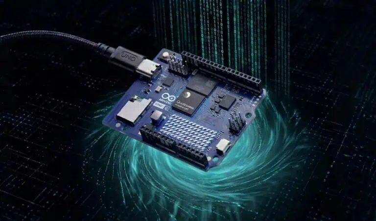
- Uno R4 WiFi: A modern evolution with a dedicated 3.3V Qwiic ecosystem.
Stop fighting the 5V past. The 3.3V future is already here.
The “No-Shifter” Strategy: ESP32 vs. R4 WiFi
This guide is your roadmap for two modern, shifter-free approaches:
- The Budget Powerhouse (ESP32): Raw power on a shoestring budget (~₹350 / $4.20).
- The Pro Plug-and-Play (Uno R4 WiFi): The ease of the Arduino ecosystem with Qwiic hardware (~₹1,350 / $16.25).
Both eliminate the need for extra components. Both host their own dashboards.
If you’re still weighing your options, check out my full Microcontroller Development Boards Guide. Otherwise, let’s build.
Phase 1: The “Budget Powerhouse” Survival Kit
Why the ESP32 is the Connectivity King
For just ₹350 ($4.20 USD), the ESP32 makes the legacy R3 look like a basic calculator. It’s the difference between a dial-up modem and a fiber-optic line; it handles WiFi and sensor data simultaneously without breaking a sweat.
Unlike the old 5V Arduinos, the ESP32’s GPIO pins operate exactly at the voltage the bmp280 barometric sensor wants (3.3V). No fighting, no smoke, just data.
The “Budget” Build Checklist (ESP32)
ESP32 Dev Board (~₹350 / $4.20 USD): This is your dual-core brain. It handles the 3.3V logic of the sensor natively, so you don’t need a level shifter.
BMP280 Sensor (~₹130 to ₹180 / $1.55 to $2.15 USD): While you can find “raw” chips for as low as ₹30, I recommend the module version with built-in voltage regulators. It’s the sweet spot for stability.
LCD1602 with I2C (~₹150 to ₹180 / $1.80 to $2.15 USD): A standard 16×2 character display. Buying it with the I2C “backpack” already soldered saves you from a wiring nightmare.
Wiring Guide: The “Dual Voltage” Setup
The bmp280 barometric sensor needs 3.3V, but the LCD1602 needs 5V to look bright. This is where most beginners panic, thinking they need two power supplies.
Wiring the ESP32 is a tight squeeze on a standard breadboard. You’ll feel the pins snap into place, but keep your jumpers short to avoid signal noise. Follow the exact mapping in the table below.
(Tip: Always keep my ESP32 pinout reference open so you don’t fry your board by mistake!)
Connection Table (ESP32)
| Component | Pin Name | ESP32 Connection | Why This Matters |
| BMP280 | VCC | 3V3 | Critical: 5V will fry this sensor instantly. |
| BMP280 | GND | GND | Shared ground. |
| BMP280 | SCL | GPIO 22 | Default I2C Clock. |
| BMP280 | SDA | GPIO 21 | Default I2C Data. |
| BMP280 | CSB | 3V3 | Pull High: This “locks” the sensor into I2C mode. |
| BMP280 | SDO | GND | Secret Step: Forces I2C Address to 0x76. |
| LCD1602 | VCC | VIN (5V) | LCD needs 5V for backlight brightness. |
| LCD1602 | GND | GND | Shared ground. |
| LCD1602 | SCL | GPIO 22 | Shares the bus with BMP280. |
| LCD1602 | SDA | GPIO 21 | Shares the bus with BMP280. |
A Note on LCD Logic (The “Handshake”)
Think of “Open Drain” like a polite handshake. The devices don’t force electricity at each other; they simply pull a shared line to ground to speak.
This polite signal control is why your 3.3V ESP32 can talk to a 5V LCD without a fight. Even though they live on different voltage levels, they share the same I2C “highway” perfectly.
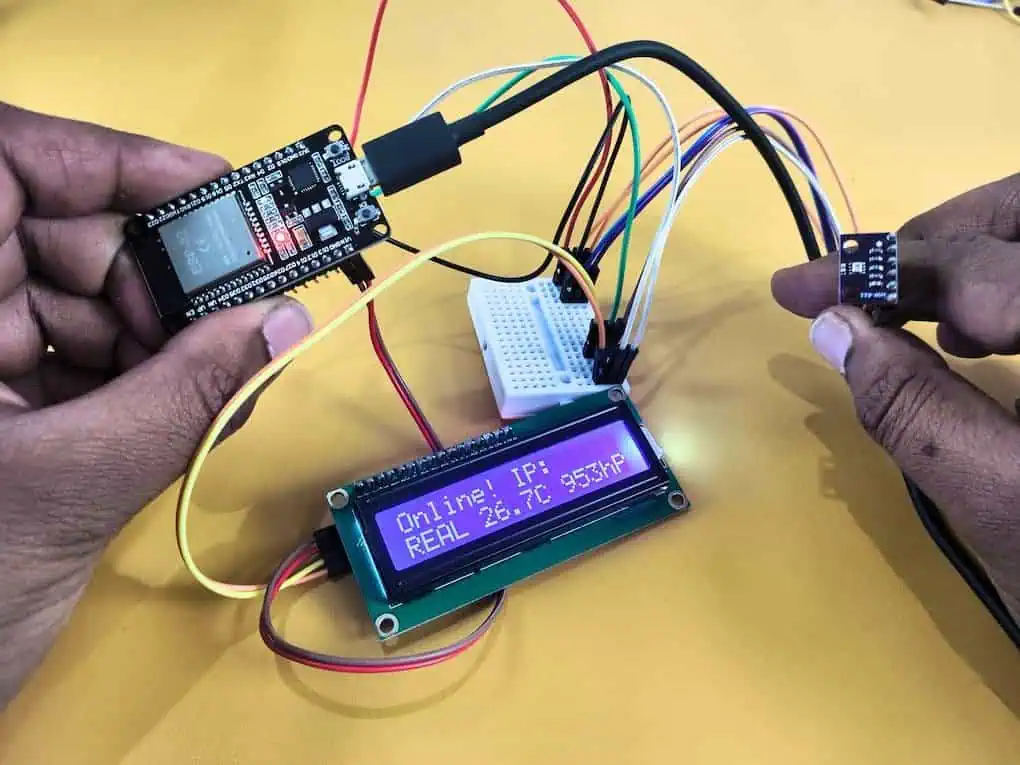
The Code: ESP32 WiFi Dashboard + LCD
This code does two things:
- Displays data on the LCD Screen (Offline Mode).
- Hosts a WiFi Dashboard you can view on your phone (Online Mode).
Prerequisites: Install Adafruit BMP280 and LiquidCrystal_I2C libraries.
C++
/*
* Project: ESP32 Weather Station (DEMO MODE)
* Hardware: ESP32, BMP280, LCD1602
* Author: Devraj
*/
#include <WiFi.h>
#include <WebServer.h>
#include <Wire.h>
#include <Adafruit_BMP280.h>
#include <LiquidCrystal_I2C.h>
// --- USER CONFIGURATION ---
const char* ssid = "YOUR_WIFI_NAME";
const char* password = "YOUR_WIFI_PASS";
// --- HARDWARE OBJECTS ---
Adafruit_BMP280 bmp;
LiquidCrystal_I2C lcd(0x27, 16, 2);
WebServer server(80);
bool sensorFound = false; // Flag to track if sensor is real
// --- DASHBOARD FUNCTION ---
void handleRoot() {
float temp, press;
if(sensorFound) {
temp = bmp.readTemperature();
press = bmp.readPressure() / 100.0F;
} else {
// Generate Random Fake Data for Testing
temp = 25.0 + (random(0, 50) / 10.0);
press = 1010.0 + (random(0, 100) / 10.0);
}
String html = "<!DOCTYPE html><html><head>";
html += "<meta http-equiv='refresh' content='2'>"; // Refresh every 2s for demo
html += "<style>body{font-family:sans-serif; text-align:center; background:#222; color:#fff; padding:50px;}";
html += ".card{background:#333; padding:20px; border-radius:10px; display:inline-block; margin:10px; width:200px;}";
html += "h1{color:#00d2ff;} .mode{color:#f39c12; font-weight:bold;}</style></head>";
html += "<body><h1>ESP32 Weather Dashboard</h1>";
if(!sensorFound) html += "<p class='mode'>RUNNING IN DEMO MODE (No Sensor)</p>";
html += "<div class='card'><h2>Temp</h2><h1>" + String(temp, 1) + " °C</h1></div>";
html += "<div class='card'><h2>Pressure</h2><h1>" + String(press, 1) + " hPa</h1></div>";
html += "</body></html>";
server.send(200, "text/html", html);
}
void setup() {
Serial.begin(115200);
// 1. Init LCD
lcd.init();
lcd.backlight();
lcd.setCursor(0,0);
lcd.print("Devraj Demo Box");
// 2. Init BMP280 (Bypass if not found)
if (bmp.begin(0x76) || bmp.begin(0x77)) {
sensorFound = true;
Serial.println("Real Sensor Found!");
} else {
sensorFound = false;
Serial.println("No Sensor Found. Switching to Demo Mode.");
lcd.setCursor(0,1);
lcd.print("MODE: DEMO DATA ");
delay(2000);
}
// 3. Connect WiFi
WiFi.begin(ssid, password);
lcd.clear();
lcd.print("Connecting WiFi");
while (WiFi.status() != WL_CONNECTED) {
delay(500);
Serial.print(".");
}
// 4. Show Success
Serial.println("\nWiFi Connected!");
Serial.print("IP: ");
Serial.println(WiFi.localIP());
lcd.clear();
lcd.setCursor(0,0);
lcd.print("Online! IP:");
lcd.setCursor(0,1);
lcd.print(WiFi.localIP());
server.on("/", handleRoot);
server.begin();
}
void loop() {
server.handleClient();
float t, p;
if(sensorFound) {
t = bmp.readTemperature();
p = bmp.readPressure() / 100.0F;
} else {
// Show static fake data on LCD to avoid flickering
t = 27.5;
p = 1012;
}
// Minimal LCD update to show life
lcd.setCursor(0,1);
if(!sensorFound) lcd.print("DEMO " + String(t,1) + "C " + String(p,0) + "hPa");
else lcd.print("REAL " + String(t,1) + "C " + String(p,0) + "hPa");
delay(200);
}Phase 2: The “Plug-and-Play” Build (Arduino Uno R4 WiFi)
Why Go Local? The “Cloud Fatigue”
I love the cloud, but sometimes, you just want speed.
When I first hooked this up to the cloud, there was a 2-second delay between blowing on the sensor and seeing the graph move. Plus, if my internet cut out (which happens often here during monsoons), my weather station went blind.
I realized: Why send data around the world just to see it in the next room?
The Arduino Uno R4 WiFi is a beast. It’s not just a microcontroller; it has enough power to act as its own Web Server. By hosting the dashboard directly on the chip, you get a masterclass in what IoT really means:
- Zero Latency: Updates are instant over your local WiFi.
- Total Privacy: No data leaves your house.
- Zero Subscription: No accounts, no “Things,” no secret keys.
The “Pro” Build Checklist (Uno R4 WiFi)
Arduino Uno R4 WiFi (~₹1,350 / $16.25 USD): The “Made in India” version is a powerhouse. It features a built-in LED matrix and a dedicated 3.3V Qwiic connector.
BMP280 Module (~₹450 to ₹500 / $5.40 to $6.00 USD): This is the high-quality, pre-calibrated version. It uses a specialized connector that prevents you from ever plugging it in backward.
Qwiic JST-SH Cable (~₹90 / $1.10 USD): A tiny 4-wire cable that clicks into place. No soldering or jumper wires are required for the sensor side of this build.
LCD1602 with I2C (~₹150 to ₹180 / $1.80 to $2.15 USD): Even on the “Pro” build, we use this classic display. It connects to the R4’s 5V headers while the sensor stays safe on the 3.3V bus.
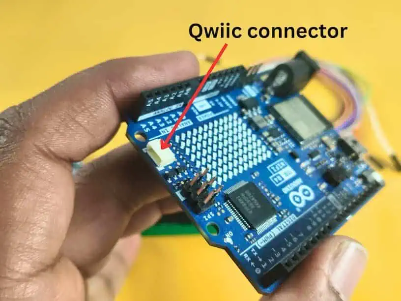
Wiring Guide: The “Bus Split” Strategy
This is the ultimate “pro move” for the R4. We are going to split our I2C bus into two separate lanes to handle the voltage difference safely without any extra components.
- Lane 1 (3.3V): We use the Qwiic Port for the delicate BMP280.
- Lane 2 (5V): We use the Standard Headers (A4/A5) for the power-hungry LCD.
Connection Master Map (Arduino Uno R4 WiFi)
| Component | Pin Name | R4 Connection | Bus Name | Why This Matters |
| BMP280 | VCC | 3.3V Pin | Power | Supplies safe 3.3V to the sensor. |
| BMP280 | GND | GND | Ground | Shared ground for the circuit. |
| BMP280 | SCL | SCL1 (Qwiic) | Wire1 | Native 3.3V clock line on the R4. |
| BMP280 | SDA | SDA1 (Qwiic) | Wire1 | Native 3.3V data line on the R4. |
| BMP280 | CSB | 3.3V Pin | I2C Lock | Pull High: Mandatory to lock the sensor into I2C mode. |
| BMP280 | SDO | GND | Address Fix | Secret Step: Forces the I2C address to 0x76. |
| LCD1602 | VCC | 5V Pin | Power | LCD logic and backlight require 5V for contrast. |
| LCD1602 | GND | GND | Ground | Shared ground for the circuit. |
| LCD1602 | SDA | A4 | Wire | Standard 5V I2C data lane. |
| LCD1602 | SCL | A5 | Wire | Standard 5V I2C clock lane. |
Real Project Experience: The “Wire1” Confusion
When I first coded this, my BMP280 wouldn’t work. I spent hours checking cables.
The “Aha!” Moment: The Qwiic port on the R4 isn’t on the main I2C bus. It has its own private bus called Wire1. If you don’t tell the code to look at Wire1, it will stare at the A4/A5 pins forever and see nothing.
The Code: R4 Dashboard + LCD
This code manages two separate I2C buses simultaneously. It displays data on the LCD using the standard pins (Wire) and reads the sensor from the Qwiic port (Wire1).
Prerequisites: Install Adafruit BMP280, LiquidCrystal_I2C and WiFiS3 libraries.
C++
/*
* Project: R4 WiFi Weather Station (Stable DHCP + Dual Bus)
* Hardware: Uno R4 WiFi, BMP280 (Qwiic), LCD1602 (Headers)
* Author: Devraj
*/
#include "WiFiS3.h"
#include <Wire.h>
#include <Adafruit_BMP280.h>
#include <LiquidCrystal_I2C.h>
// --- USER CONFIGURATION ---
const char ssid[] = "YOUR_WIFI_NAME";
const char pass[] = "YOUR_WIFI_PASS";
// --- HARDWARE OBJECTS ---
Adafruit_BMP280 bmp(&Wire1); // BMP280 on Wire1 (Qwiic Port)
LiquidCrystal_I2C lcd(0x27, 16, 2); // LCD on Wire (Headers A4/A5)
WiFiServer server(80);
bool sensorFound = false;
void setup() {
Serial.begin(115200);
// 1. Wait for Serial Monitor to be open
while (!Serial) { delay(10); }
delay(1000); // Extra buffer for R4 USB stability
Serial.println("\n--- Devraj's R4 Project: Stable Start ---");
// 2. Initialize LCD (5V Headers)
lcd.init();
lcd.backlight();
lcd.setCursor(0,0);
lcd.print("R4 System Init");
// 3. Initialize BMP280 (3.3V Qwiic Bus)
Wire1.begin();
if (bmp.begin(0x76) || bmp.begin(0x77)) {
sensorFound = true;
Serial.println("Success: Real BMP280 Detected.");
} else {
sensorFound = false;
Serial.println("Warning: No Sensor Found. Demo Mode Active.");
lcd.setCursor(0,1);
lcd.print("MODE: DEMO DATA ");
delay(2000);
}
// 4. Connect to WiFi with DHCP Fix
Serial.print("Connecting to: ");
Serial.println(ssid);
lcd.clear();
lcd.print("WiFi Connecting");
WiFi.begin(ssid, pass);
// Connection timeout logic (approx 20 seconds)
int timeout = 0;
while (WiFi.status() != WL_CONNECTED && timeout < 40) {
delay(500);
Serial.print(".");
timeout++;
}
// CRITICAL: Give router time to assign the IP address
delay(3000);
if (WiFi.status() == WL_CONNECTED) {
Serial.println("\nWiFi Connected!");
IPAddress ip = WiFi.localIP();
// Double-check for the 0.0.0.0 "Ghost IP"
if (ip[0] == 0) {
Serial.println("Retrying DHCP...");
delay(2000);
ip = WiFi.localIP();
}
Serial.print("Dashboard URL: http://");
Serial.println(ip);
lcd.clear();
lcd.print("Online! IP:");
lcd.setCursor(0,1);
lcd.print(ip);
server.begin();
} else {
Serial.println("\nConnection Failed! Check SSID/Pass.");
lcd.clear();
lcd.print("WiFi Failed!");
}
}
void loop() {
WiFiClient client = server.available();
// Read Real or Fake Data
float temp, press;
if(sensorFound) {
temp = bmp.readTemperature();
press = bmp.readPressure() / 100.0F;
} else {
temp = 28.5; // Static test data
press = 1013;
}
// Update LCD Display
lcd.setCursor(0,0);
lcd.print("T: " + String(temp,1) + "C ");
lcd.setCursor(0,1);
if(!sensorFound) lcd.print("DEMO " + String(press,0) + "hPa ");
else lcd.print("P: " + String(press,0) + "hPa ");
// Serve Web Page
if (client) {
boolean currentLineIsBlank = true;
while (client.connected()) {
if (client.available()) {
char c = client.read();
if (c == '\n' && currentLineIsBlank) {
client.println("HTTP/1.1 200 OK");
client.println("Content-Type: text/html");
client.println("Connection: close");
client.println("Refresh: 5");
client.println();
client.println("<!DOCTYPE HTML><html><head><style>");
client.println("body{font-family:sans-serif; text-align:center; background:#222; color:#fff; padding:50px;}");
client.println(".card{background:#333; padding:20px; border-radius:10px; margin:10px; display:inline-block; width:200px;}");
client.println("h1{color:#f39c12;}</style></head>");
client.println("<body><h1>R4 Weather Dashboard</h1>");
client.println("<div class='card'><h2>Temp</h2><h1>" + String(temp, 1) + "</h1><p>°C</p></div>");
client.println("<div class='card'><h2>Pressure</h2><h1>" + String(press, 0) + "</h1><p>hPa</p></div>");
client.println("</body></html>");
break;
}
if (c == '\n') currentLineIsBlank = true;
else if (c != '\r') currentLineIsBlank = false;
}
}
delay(10);
client.stop();
}
}Problems Nobody Talks About (And Real Fixes)
Even with the best code, physics can ruin your project. Here are the “ghost” problems I’ve spent months solving.
Problem 1: The “Drifting Altimeter” (Light Sensitivity)
The Catch: Did you know the BMP280 is afraid of the light? The MEMS diaphragm inside the silver can is actually photo-sensitive. If direct sunlight hits the vent hole, the pressure reading shifts.
The Fix: Place a small piece of dark, open-cell foam over the sensor. It lets air through but blocks light.
Problem 2: The “Hot Sensor” (Self-Heating)
The Catch: If you measure too fast, you fry your data. Constant electrical activity creates heat, raising the sensor’s temperature by 1–2°C above room temp.
The Fix: In your code, do not poll the sensor every 10ms. A 2-second delay allows the chip to cool down.
Your Build Checklist & Cost Breakdown
Building a weather station shouldn’t break the bank. Here is exactly what I spent on my builds.
The “Budget” Build (ESP32)
- ESP32 Dev Board: ~$4.00 USD (₹350 INR)
- BMP280 Module: ~$2.00 USD (₹180 INR)
- LCD1602 (I2C): ~$4.00 USD (₹350 INR)
- Total: ~$10.00 USD (₹880 INR)
The “Pro” Build (Uno R4 WiFi)
- Arduino Uno R4 WiFi (Made in India): ~$16.00 USD (₹1,350 INR)
- BMP280 (Qwiic Version): ~$5.00 USD (₹450 INR)
- Qwiic Cable: ~$1.00 USD (₹90 INR)
- LCD1602 (I2C): ~$4.00 USD (₹350 INR)
- Total: ~$26.00 USD (₹2,240 INR)
Final Word: Just Build It
The BMP280 is a masterclass in modern engineering. It taught me more about 3.3V logic and environmental physics than any textbook.
Whether you choose the ESP32 for its raw value (₹350), or you dive into the robust ecosystem of the Arduino Uno R4 WiFi (₹1,350), the goal is the same: stop guessing and start measuring.
My advice? Don’t wait for the “perfect” enclosure. Wire it up tonight. Lift the sensor. Watch the pressure drop. That’s where the real learning happens.
“Wait, Why Isn’t It Working?” – Troubleshooting My Own 2 AM Failures
My Serial Monitor is just showing “????” or random gibberish. What’s wrong?
I forgot that the ESP32 and Arduino Uno R4 WiFi have different default baud rates. While most old Uno R3 projects use 9600, these modern boards are much faster. I spent 20 minutes “fixing” my code when the only problem was that my Serial Monitor was set to 9600 instead of 115200.
I’m using the R4 WiFi, and my LCD is working, but the BMP280 is invisible. Why?
This was my biggest “head-desk” moment. I used the Qwiic cable for the sensor but kept using Wire.begin() in my code. On the R4, the Qwiic port is physically wired to a completely separate bus. You must call Wire1.begin() and use bmp.begin(0x76, &Wire1). If you don’t add that “1,” the board looks at the empty A4/A5 pins forever.
My ESP32 keeps rebooting every time the WiFi tries to connect. Is it broken?
I tried to power the whole setup—ESP32, LCD, and BMP280—just from my laptop’s USB port. WiFi chips pull a lot of current during the “handshake” with the router. My laptop port couldn’t keep up, the voltage sagged, and the board crashed. I solved it by using a high-quality 5V 2A mobile charger adapter to power the board.
Why is my pressure reading jumping around when I move the sensor?
I didn’t realize that static electricity is a nightmare for the bmp280 barometric sensor. I was holding the sensor module directly with my fingers while testing. The heat from my skin and the static from my hands caused the readings to drift by 3-4 hPa instantly. Use plastic tweezers or let it sit on a breadboard for 5 minutes to get a stable “room” reading.
The LCD backlight is on, but I don’t see any letters. Did I fry it?
I thought I had a dead LCD. Turns out, the potentiometer (the little blue dial on the back of the I2C adapter) was turned all the way to zero. Even though the code was perfect, the contrast was so low the text was invisible. Give that dial a small turn with a screwdriver before you assume the hardware is dead!