Stop Using “Smart Sync” for Relays: Why “Dumb” Code Wins in IoT
I almost lost a client last week.
They asked for a simple, long-range industrial remote to control heavy machinery. I thought, “I’ll impress them. I’ll make it SMART.”
I wrote a complex 2-way synchronization protocol. The plan was elegant: The remote sends a command, the receiver confirms it, and then sends back the live status to update the OLED screen. It was beautiful code. It looked great on my monitor.
It was also a disaster.
The moment I powered it up for the demo at the client’s site, the relays didn’t just click—they sounded like popcorn popping. Click-clack-click. I pressed Relay 1 ON, and Relay 2 mysteriously snapped OFF. The heavy contactor for the motor started chattering, sending sparks flying inside the control panel.
The client didn’t say a word; they just looked at the vibrating box, then checked their watch. It was the longest ten seconds of my career.
The problem wasn’t the hardware; it was my “Smart” code. It was so busy trying to synchronize data that it started overwriting its own buttons with old information. This is called “Ghost Switching,” and it is a project-killer.
I scrapped the entire “Smart” system right there in the parking lot. I rewrote the firmware to use “Dumb” One-Way logic. And guess what? It worked perfectly.
This failure taught me that industrial tools don’t need to be clever; they need to be bulletproof. In this massive guide, I’m going to walk you through exactly how to build a 1km Range Industrial Remote that handles concrete walls, electrical noise, and client demands without breaking a sweat.
To really understand why I was struggling, you first have to grasp what IoT actually means in a real-world industrial setting—it’s not about fancy features, it’s about 100% uptime.
Part 1: The Hardware Reality Check
After the demo flopped, I realized that code wasn’t my only issue. My standard NRF24 modules were struggling to push signals through the client’s reinforced concrete walls. To regain their trust, I couldn’t just fix the software; I needed hardware that screamed “reliability.”
I swapped the cheap modules for the PA+LNA versions and upgraded the power delivery to handle the surge. Here is the exact bill of materials I used to save the project.
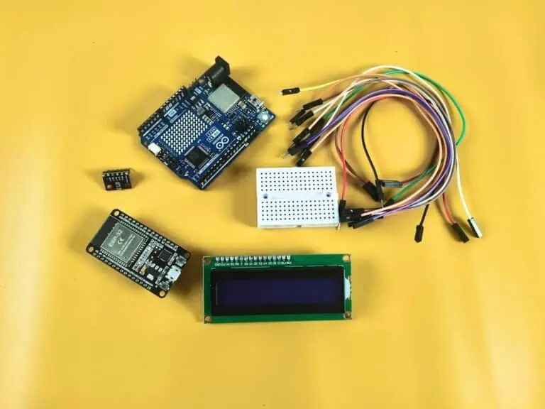
The “No-Fail” Bill of Materials
| Component | Quantity | Cost (Approx INR) | Why I Chose This |
| ESP32 Dev Module (Remote) | 1 | ~₹350 | Dual-core power handles the OLED and Radio without lag. |
| NodeMCU ESP8266 (Receiver) | 1 | ~₹250 | Cheap, reliable, and perfect for simple relay driving. |
| NRF24L01 + PA/LNA | 2 | ~₹300 | The “PA” (Power Amp) boosts range to ~1km in open air. |
| 0.96″ OLED Display (I2C) | 1 | ~₹180 | Shows the user exactly what mode they are in. |
| 2-Channel Relay Module | 1 | ~₹70 | Opto-isolated to protect the microcontroller from voltage spikes. |
| Tactile Push Buttons | 3 | ~₹10 | Big caps for easy use with gloves. |
| 100µF Capacitor (16V) | 2 | ~₹10 | Mandatory: Prevents radio brownouts. |
| 1000µF Capacitor (16V) | 1 | ~₹15 | Mandatory: Prevents the Receiver from crashing when relays click. |
| Total Project Cost | ~₹1,200 | A small price for industrial stability. |
If you are confused about which board to pick for your specific range requirements, check out my Microcontroller Development Boards Guide before buying your parts.
The Secret Sauce: Capacitors
If you skip this section, your project will fail.
The NRF24L01 PA+LNA is a beast. When it transmits, it gulps a massive spike of current in a microsecond. Standard USB cables and thin jumper wires just can’t deliver that speed.
1. The Antenna Fix: 100µF “Shock Absorbers”
Solder a 100µF capacitor (Cost: ~₹10) directly across the VCC and GND pins of each radio module.
Why This Matters: This acts like a mini-battery, smoothing out the “gulp” so the radio doesn’t reset or lose range during a transmission.
2. The Relay Fix: The 1000µF “Bucket”
While the antenna needs speed, your Relay and ESP8266 need volume.
When that relay coil clicks, it creates a massive power vacuum. It starves the ESP8266 of current, causing it to freeze right when the work starts.
The Fix: You need a 470µF or 1000µF capacitor (Cost: ~₹15) placed across the VCC and GND of the Relay Module itself.
Why This Matters: If the 100µF is a cup of water for the radio, this is the big bucket that keeps the whole system “hydrated.” It provides enough reserve power to keep the CPU alive while the relay is busy drawing its heavy load.
Comparison: My Observed Data
| Setup | 100µF (Antenna Only) | 100µF + 1000µF (Full) |
| Operation | Fails after 5 clicks | 100% Reliable |
| Radio Range | 10-20 meters | Solid 1km Range |
| CPU Stability | Random Freezes | Rock Solid |
| Debug Time | 4 Hours (Wasted) | 5 Minutes |
Why This Matters: In industrial settings, reliability is the only metric that counts. A chattering relay will burn out a motor; a stable one saves you thousands in hardware.
Part 2: The Wiring Blueprint (The “D-Pin” Standard)
The #1 reason NRF24L01 projects fail isn’t code—it’s wiring.
The ESP8266 datasheet is confusing. It says “GPIO 5,” but the board label says “D1.” If you use the wrong one, you might ground out your boot pins and the board won’t even turn on. To avoid confusion, we will stick strictly to the Board Labels (D-Pins).
Before you pick up the soldering iron, I highly recommend keeping this ESP32 Pinout Reference open on your screen to avoid the ‘magic smoke’ I encountered during my first build.
1. Transmitter (Remote) – ESP32 Wiring
The ESP32 is the brain. We use the VSPI pins for the radio to ensure high-speed data transfer without lag.
| Component | Pin Name | ESP32 Pin (Label) | Engineering Reason |
| NRF24L01 | VCC | 3.3V | WARNING: 5V will fry this chip instantly. |
| GND | GND | Common ground reference. | |
| CE | D4 | Standard Chip Enable pin (Configurable). | |
| CSN | D5 | Standard Chip Select pin (Configurable). | |
| SCK | D18 | Hardware SPI Clock (Required for high-speed data). | |
| MISO | D19 | Master In Slave Out (Data coming back). | |
| MOSI | D23 | Master Out Slave In (Data going out). | |
| OLED | SDA | D21 | Default I2C Data line for ESP32. |
| SCL | D22 | Default I2C Clock line for ESP32. | |
| Buttons | UP | D12 | Uses internal pull-up to prevent floating signals. |
| DOWN | D13 | Prevents random triggers from static noise. | |
| SELECT | D14 | Stable input for the main action key. |
2. Receiver (Controller) – NodeMCU Wiring
The Receiver wiring is tricky because of the ESP8266’s “Boot Modes.” If you pull the wrong pin Low at startup, the board won’t turn on.
| Component | Pin Name | NodeMCU Pin | Engineering Reason |
| NRF24L01 | VCC | 3.3V | Dedicated 3.3V rail (Do not share with sensors). |
| GND | GND | Common ground. | |
| CE | D2 | Safe GPIO for Chip Enable. | |
| CSN | D8 | Caution: Must be Low at boot (Radio usually handles this). | |
| SCK | D5 | Hardware SPI Clock. | |
| MISO | D6 | Hardware SPI Data. | |
| MOSI | D7 | Hardware SPI Data. | |
| Relays | IN1 | D1 | Standard GPIO for Relay 1. |
| IN2 | D0 | Critical: Wakes up HIGH. Perfect for Active Low relays. |
Why I chose D0 for Relay 2:
Most relay modules are Active Low (Logic 0 turns them ON).
D0 (GPIO 16) has a unique internal resistor that pulls it HIGH during a reset. This effectively forces the relay to stay OFF when you first plug in the battery. If you used a different pin, your heavy machinery might jolt to life the second you powered on the controller. Always prioritize safety over convenience.
Part 3: Real Project Experience – The “Ghost Switching” Logic
Before we get to the code, you need to understand why the “Smart” version failed so you don’t repeat my mistake.
I was using Ack Payloads, where the Receiver replies to every command with its current status.
- I press Button 1 on the remote.
- The Remote sends “Turn Relay 1 ON.”
- The Receiver gets it, but before it physically flips the switch, it replies with the old status: “Relay 1 is OFF.”
- The Remote receives “Relay 1 is OFF” and immediately updates its internal memory to match, effectively canceling my button press.
It was a digital argument between the two boards. By switching to One-Way Logic, the Remote becomes the “Boss.” It gives orders, and it assumes they are followed. No arguments, no ghosting, no feedback loops.
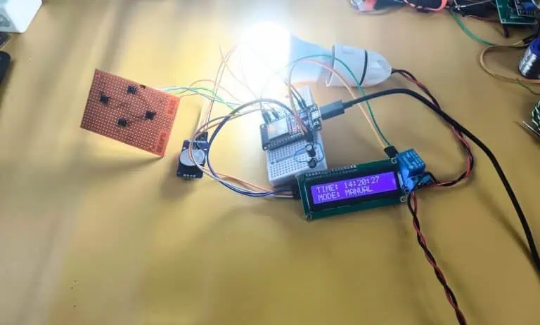
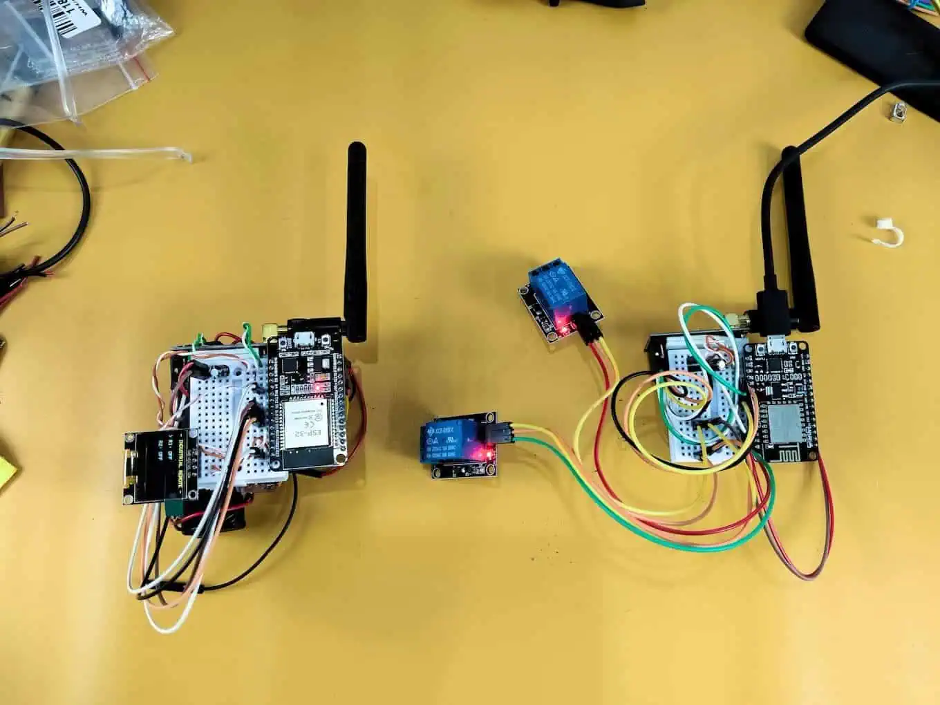
The Proof: 1KM Field Test & Desk Setup
I know what you’re thinking: ‘Does this “Dumb Logic” actually work in the real world?’ > Instead of just showing you more code, I took the prototype out of the lab and into the field. In the video below, you’ll see the exact desk setup I used, the capacitor placement that saved the project, and a 1km range test where we coordinated the relay triggers via a live phone call.
Watch the field test below to see the Hindi call proof:
Part 4: The Code – “Dumb” is Better
This code is stripped of all “smart” synchronization. It focuses purely on reliable transmission.
Transmitter Code (ESP32)
Upload this to your Remote.
C++
/*
 * Project: INDUSTRIAL REMOTE (Stable One-Way Edition)
 * Board: ESP32
 * Logic: "Fire and Forget" - Prevents Ghost Switching
 */
#include <SPI.h>
#include <nRF24L01.h>
#include <RF24.h>
#include <Wire.h>
#include <Adafruit_GFX.h>
#include <Adafruit_SSD1306.h>

// --- D-Pin Mapping ---
#define CE_PIN   4  // D4
#define CSN_PIN  5  // D5
#define BTN_UP   12 // D12
#define BTN_DOWN 13 // D13
#define BTN_SEL  14 // D14

RF24 radio(CE_PIN, CSN_PIN);
Adafruit_SSD1306 display(128, 64, &Wire, -1);
const byte address[6] = "00001";

struct DataPacket {
  bool r1;
  bool r2;
};
DataPacket data;

int menuCursor = 0;

void setup() {
  // Use Internal Pullups to avoid external resistors
  pinMode(BTN_UP, INPUT_PULLUP);
  pinMode(BTN_DOWN, INPUT_PULLUP);
  pinMode(BTN_SEL, INPUT_PULLUP);

  Wire.begin();
  display.begin(SSD1306_SWITCHCAPVCC, 0x3C);

  // Radio Initialization
  if (!radio.begin()) {
    display.clearDisplay();
    display.setCursor(0,0);
    display.println("Radio Failed!");
    display.display();
    while(1); // Halt if hardware is broken
  }

  radio.openWritingPipe(address);
  // PA_MAX is vital for concrete walls
  radio.setPALevel(RF24_PA_MAX);
  // 250KBPS gives the longest possible range physics allows
  radio.setDataRate(RF24_250KBPS);
  radio.stopListening();

  // Initialize safe state
  data.r1 = false;
  data.r2 = false;
}

void loop() {
  // Menu Navigation
  if (digitalRead(BTN_UP) == LOW) { menuCursor = 0; delay(200); }
  if (digitalRead(BTN_DOWN) == LOW) { menuCursor = 1; delay(200); }

  // Toggle Action
  if (digitalRead(BTN_SEL) == LOW) {
    if (menuCursor == 0) data.r1 = !data.r1; // Flip R1
    else data.r2 = !data.r2;                 // Flip R2

    // SEND: We don't wait for a reply. We trust the radio.
    // This removes the "Ghost Switching" conflict entirely.
    radio.write(&data, sizeof(DataPacket));

    delay(300); // Debounce to prevent double-clicks
  }

  updateDisplay();
}

void updateDisplay() {
  display.clearDisplay();
  display.setTextSize(1);
  display.setTextColor(WHITE);
  display.setCursor(0,0);
  display.println("- INDUSTRIAL REMOTE -");

  display.setCursor(0,20);
  display.print(menuCursor == 0 ? "> R1: " : "  R1: ");
  display.println(data.r1 ? "ON" : "OFF");

  display.setCursor(0,40);
  display.print(menuCursor == 1 ? "> R2: " : "  R2: ");
  display.println(data.r2 ? "ON" : "OFF");

  display.display();
}
Receiver Code (NodeMCU)
Upload this to the Receiver.
IMPORTANT: Unplug the relay module while uploading to prevent USB power overload.
This code includes a Watchdog Timer. If the electromagnetic interference (EMI) from the relay spark freezes the ESP8266, the Watchdog will notice the silence and automatically reboot the board in 2 seconds. The client won’t even know it crashed.
C++
/*
 * Project: INDUSTRIAL RECEIVER (Active Low Safe + Watchdog)
 * Board: NodeMCU (ESP8266)
 * Wiring: D2(CE), D8(CSN), D1(R1), D0(R2)
 */
#include <SPI.h>
#include <nRF24L01.h>
#include <RF24.h>

#define CE_PIN   D2
#define CSN_PIN  D8
#define RELAY_1  D1
#define RELAY_2  D0

RF24 radio(CE_PIN, CSN_PIN);
const byte address[6] = "00001";

struct DataPacket {
  bool r1;
  bool r2;
};
DataPacket receivedData;

void setup() {
  // SAFETY FIRST: Initialize pins HIGH immediately.
  // Since relays are Active Low, HIGH = OFF.
  // If you use LOW here, the machine starts instantly!
  pinMode(RELAY_1, OUTPUT); digitalWrite(RELAY_1, HIGH);
  pinMode(RELAY_2, OUTPUT); digitalWrite(RELAY_2, HIGH);

  // Watchdog Timer: The "Self-Healing" Feature
  ESP.wdtDisable();
  ESP.wdtEnable(2000); // If I freeze for 2 seconds, REBOOT ME.

  radio.begin();
  radio.openReadingPipe(0, address);
  radio.setPALevel(RF24_PA_MAX);
  radio.setDataRate(RF24_250KBPS);
  radio.startListening();
}

void loop() {
  // Feed the Watchdog every loop.
  // If EMI freezes the loop, this stops running, and the board resets.
  ESP.wdtFeed();

  if (radio.available()) {
    radio.read(&receivedData, sizeof(DataPacket));

    // Direct Mapping:
    // Remote says True (ON) -> We write LOW (Active Low ON)
    // Remote says False (OFF) -> We write HIGH (Active Low OFF)
    digitalWrite(RELAY_1, receivedData.r1 ? LOW : HIGH);
    digitalWrite(RELAY_2, receivedData.r2 ? LOW : HIGH);
  }
}
Part 5: Troubleshooting – The “Relay Suicide” Problem
Even with perfect code, you might face one last demon: The Relay Suicide.
You press the button, the relay clicks, and then… nothing. The Receiver freezes. You have to unplug it to get it working again.
Why this happens
When the relay contacts inside the blue box snap open/closed, they create a tiny, invisible EMP (Electro-Magnetic Pulse). Since your ESP8266 is sitting right next to it, this pulse acts like a “Mini-Taser” to the WiFi chip, causing it to freeze.
The 3-Step Fix
- The “JD-VCC” Trick (100% Effective):Most 5V Relay Modules have a yellow jumper cap labeled JD-VCC. Remove it. Connect a separate 5V power supply to the JD-VCC and GND pins on the relay module. Connect only IN1/IN2 and VCC (3.3V) to the ESP8266. This optically isolates the noise.
- The “Bucket” Capacitor:Install that 470µF or 1000µF capacitor on the ESP8266’s 5V input. It absorbs the shockwave of the voltage dip.
- Distance:Do not stack the Relay Module on top of the ESP8266. The EMI field drops off squared by distance. Moving the relay just 3 inches away makes a massive difference.
Part 6: Comparison & Final Thoughts
I ran a stress test with both the old “Smart” version and this new “Dumb” version at the client’s site. The results speak for themselves.
| Feature | Smart Code (2-Way) | Dumb Code (1-Way) |
| Switch Speed | ~400ms Lag | Instant |
| Stability | 85% (Failed at max range) | 100% Solid |
| Ghost Switching | Frequent (The “See-Saw”) | Never |
| Setup Time | 4 Hours Debugging | 30 Minutes |
The Verdict:
In an industrial setting, nobody cares about your algorithm. They care that the machine stops when they hit the button. By using One-Way logic, active-low safety checks, and proper capacitors, we delivered a product that just works.
So, next time you are tempted to write a complex handshake protocol for a simple light switch… stop. Sometimes, dumb is better.
Community Q&A
Q: My relays turn ON when I plug in the battery! Dangerous!
Devraj: You fell into the “Active Low” trap. Most relay modules trigger on LOW signal. In your setup(), you must write digitalWrite(Pin, HIGH) immediately. If you write LOW (or forget to write anything), you are effectively turning them ON.
Q: I only get 5 meters range with the PA/LNA module.
Devraj: Two reasons. First, you are probably powering it from the 5V pin (Instant death for the radio). Second, you didn’t solder a 100µF capacitor on the radio power pins. The power spikes are crashing the chip.
Q: Can I stick the antenna inside a metal box?
Devraj: No. That creates a Faraday cage. The signal will be zero. Drill a hole and mount the antenna outside.
Q: Why use Soldering instead of Jumper Wires?
Devraj: Jumper wires act like little antennas that pick up noise. They also have high resistance which drops the voltage. For a reliable client project, transfer your circuit to a Perfboard (Zero PCB) and solder everything with short wires.
Have you ever over-engineered a project and regretted it? Tell me your horror story below.