How to Build a Life-Saving LPG Gas Leakage Detector Using Arduino (The Ultimate 2026 Guide)
Does the smell of rotten eggs terrify you? It should.
Last winter, I walked into my kitchen at 2 AM for a glass of water and froze. The smell was unmistakable. My wife had heated milk hours ago, the milk boiled over, extinguished the flame, but the knob—the silent killer—was still turned ON. The kitchen was slowly filling with LPG.
That night, I didn’t sleep. I sat at my workbench, looked at my pile of microcontrollers, and made a decision: Never again.
In the age of Self-Driving Cars and AI Chatbots, why are we still manually checking if the stove is off? This is exactly what IoT means—taking dumb objects and giving them a brain.
In this comprehensive guide, I am going to show you how to build a robust, industrial-grade LPG gas leakage detector using Arduino. But we aren’t stopping there. Most tutorials just blink a tiny LED when they smell gas. Boring.
We are going to build a system that ACTS.
When this device detects a leak, it won’t just beep. It will physically rotate a servo motor attached to your gas regulator and shut off the main supply automatically.
If you are looking for a gas leakage detector using Arduino project that is more than just a toy, you have found it. Let’s build something that actually saves lives.
Why Build This Instead of Buying It?
You might be thinking, “Devraj, can’t I just buy an alarm on Amazon for ₹500?”
Sure you can. But here is the catch:
- They are Passive: They scream, but if you aren’t home to hear it, your house still fills with gas.
- No Cut-off Mechanism: They don’t stop the leak; they just announce it.
- The “DIY” Advantage: By building it yourself, you can customize the sensitivity. You can add WiFi later to get WhatsApp alerts. You can hook it up to a massive industrial siren if you want.
This project isn’t just about electronics; it’s about peace of mind.
See It In Action: Step-by-Step Video Guide
Before you buy the parts, watch the full build process below. I walk you through the “Auto-Reset” logic, show you the Servo Mounting hack for stiff regulator knobs, and demonstrate the live gas test where the system shuts off automatically.
Pro Tip: Pause the video at 0:53 to see the wiring diagram clearly on your screen!
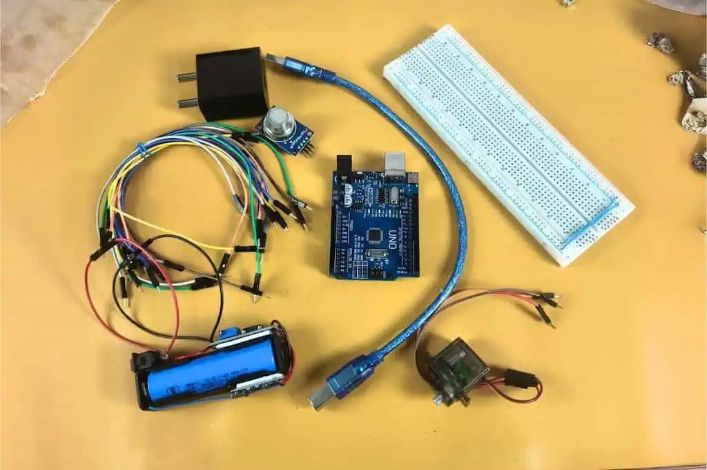
Phase 1: The Shopping List (Bill of Materials)
To build a reliable LPG gas leakage detector for home, we need components that won’t fail after a week. I have tested dozens of parts, and here is my “Devraj-Approved” list.
Prices are estimated based on Indian electronics markets (Chandni Chowk/SP Road) as of 2026.
1. The Brain: Arduino Uno R3
- Why: It’s the tank of the microcontroller world. It runs on 5V logic, which matches our sensor perfectly. If you are curious about how it stacks up against others, check my Microcontroller Development Boards Guide. Don’t use an ESP32 for this specific version unless you want to deal with voltage shifting (though I love the ESP32, the Uno is safer for beginners here).
- Cost: ₹450 – ₹550.
2. The Nose: MQ-2 Gas Sensor Module
- Why: The MQ-2 is a metal oxide semiconductor sensor. It is sensitive to LPG, Propane, Hydrogen, and even Smoke.
- The Catch: It has a heating element inside. It needs to get hot to work.
- Cost: ₹90 – ₹120.
3. The Muscle: MG90S Metal Gear Servo
- Why: Do NOT use the blue plastic SG90 servo. I repeat: Do NOT use the SG90. A gas regulator knob is stiff. The plastic gears of an SG90 will strip instantly. The MG90S has brass/metal gears and higher torque (stopping power).
- Cost: ₹150 – ₹200.
4. The Face: 16×2 LCD Display with I2C Adapter
- Why: You need to see the real-time gas values to calibrate the system. The I2C adapter is crucial because it reduces the wiring from 16 wires down to just 4.
- Cost: ₹200 – ₹250.
5. The “Secret Sauce”: 1000µF Capacitors (16V or higher)
- Why: This is the part 99% of tutorials miss. Servos draw huge spikes of power. Without these capacitors, your Arduino will brown out (restart) every time the motor moves.
- Cost: ₹10.
Total Project Cost: Under ₹1,200
(Comparison: A smart gas valve from a big brand costs ₹8,000+).
Phase 2: Understanding the Hardware
Before we plug wires in, let’s understand what we are plugging in.
The MQ-2 Sensor: How It Sniffs
The MQ-2 looks like a little mesh drum. Inside that mesh is a coil made of Tin Dioxide (SnO2). When this coil is heated (which is why we need 5V), it reacts chemically with combustible gases.
- Clean Air: The resistance of the sensor is high. (Arduino reads a low voltage).
- Gas Present: The resistance drops drastically. (Arduino reads a high voltage).
Real Project Experience:
When you first power this sensor, it will smell like burning plastic. Do not panic. This is the “burn-in” phase. The factory protective coating is burning off. Leave it powered on for 24 hours for the best accuracy, but for testing, 30 minutes is enough.
The Servo Motor: The Mechanical Hand
We are using the MG90S. It has three wires:
- Brown: Ground (GND)
- Red: Power (4.8V – 6V)
- Orange: Signal (PWM)
The challenge here isn’t the electronics; it’s the Torque. An LPG knob requires a significant amount of force to turn. The MG90S provides about 1.8kg/cm of torque. This is just enough for a well-oiled regulator, but we will use a mechanical trick (leverage) later to make it easier.
Phase 3: The Circuit Diagram & Wiring
This is where beginners usually fry their boards. Pay attention.
We are dealing with a mix of Analog signals (the sensor), Digital Protocols (the I2C LCD), and High Current (the Servo). If you wire this wrong, the magic smoke will escape.
The “Anti-Reset” Power Rail
The most critical part of this build is the power distribution.
- Take your breadboard.
- Connect the Arduino 5V pin to the Red Rail (+).
- Connect the Arduino GND pin to the Blue Rail (-).
- Insert the Capacitors: Plug the 1000µF capacitors directly into the Red and Blue rails. Watch the polarity! The side with the White Stripe goes to Minus (-).
Pin Connections Table
| Component | Pin Label | Connect To (Arduino Uno) | Notes |
| MQ-2 Sensor | VCC | 5V Rail | Needs stable heat. |
| GND | GND Rail | ||
| A0 | Pin A0 | Analog Signal. | |
| D0 | Empty | Do not connect! | |
| MG90S Servo | Red | 5V Rail | MUST be near capacitors. |
| Brown | GND Rail | ||
| Orange | Pin 9 | PWM capable pin. | |
| LCD Display | VCC | 5V Rail | |
| GND | GND Rail | ||
| SDA | Pin A4 | Or the dedicated SDA pin. | |
| SCL | Pin A5 | Or the dedicated SCL pin. |
Devraj’s Warning:
Never power the Servo directly from the Arduino’s 5V pin without capacitors. The Arduino voltage regulator isn’t designed to handle motor spikes. If your LCD flickers when the motor moves, you need bigger capacitors!
The “Pro” Power Upgrade (Highly Recommended)
If you want your LPG gas leakage detector to be 100% reliable (and not just a prototype), you should use a Separate Power Supply for the servo motor.
Devraj’s Golden Rule for Separate Power:
WARNING: If you use a separate power supply, you MUST connect the Grounds (GND) together.
Connect the External Supply GND to the Arduino GND.
If you don’t do this, the “Orange” signal wire has no reference point, and your servo will jitter uncontrollably like it’s possessed.
Phase 4: The Code (The Brains of the Operation)
Writing code for safety devices is different from writing code for blinking LEDs. We need Hysteresis.
What is Hysteresis?
Imagine your gas level is hovering right at the danger limit (let’s say 600).
- Gas Level: 601 (DANGER! Valve Close)
- Gas Level: 599 (SAFE! Valve Open)
- Gas Level: 601 (DANGER! Valve Close)
If we don’t handle this, your servo will jitter back and forth until it burns out. We fix this by having a “Trigger Threshold” (600) and a separate “Reset Threshold” (500). The valve closes at 600 but won’t open again until the air is really clean (below 500).
The Full Sketch
Copy this code into your Arduino IDE. You will need the LiquidCrystal_I2C library installed.
C++
#include <Wire.h>
#include <LiquidCrystal_I2C.h>
#include <Servo.h>

// --- THE MISSING SECTION (Global Variables) ---
const int gasPin   = A0;    // MQ2 sensor on Analog Pin 0
const int servoPin = 9;     // Servo signal on Digital Pin 9
int threshold      = 600;   // Danger trigger point
int safeBuffer     = 500;   // Level to return to safe position

// Define the LCD and Servo objects
LiquidCrystal_I2C lcd(0x27, 16, 2);
Servo gasValve;

// Keep track of the valve state
bool isValveClosed = false;

void setup() {
  Serial.begin(9600);

  // Initialize LCD
  lcd.init();
  lcd.backlight();

  // Initialize Servo
  gasValve.attach(servoPin);
  gasValve.write(0); // Start in OPEN position

  lcd.setCursor(0, 0);
  lcd.print("System Ready...");
  delay(2000);
  lcd.clear();
}

void loop() {
  // Read the MQ2 (This is where your error was!)
  int gasValue = analogRead(gasPin);

  // Display current reading on Top Row
  lcd.setCursor(0, 0);
  lcd.print("Gas Level: ");
  lcd.print(gasValue);
  lcd.print("    "); // Clear old digits

  // Safety Logic on Bottom Row
  lcd.setCursor(0, 1);

  // 1. DANGER: Gas is high, close the valve
  if (gasValue > threshold) {
    gasValve.write(90);
    lcd.print("STATUS: DANGER!");
    isValveClosed = true;
    Serial.println("!!! GAS ALERT: Valve Closed !!!");
  }

  // 2. AUTO-RESET: Return to 0 only if air is clean AND it was closed
  else if (gasValue < safeBuffer && isValveClosed == true) {
    gasValve.write(0);
    lcd.print("STATUS: RESET  ");
    delay(1000);
    isValveClosed = false;
  }

  // 3. NORMAL: Everything is fine
  else if (isValveClosed == false) {
    lcd.print("STATUS: SAFE   ");
  }

  delay(500);
}
Phase 5: The Mechanical Mounting (The Hard Part)
This is where 90% of beginners fail. You have the code working, the servo is moving, but how do you attach a square plastic motor to a round gas knob?
Do NOT glue the servo to the knob.
If you glue it, you can never turn the gas on manually if the power goes out.
The “Devraj” Zip-Tie Method:
- The Base: I used a small piece of wood (or 3D printed plastic) and zip-tied it to the neck of the gas regulator. This holds the Servo body stationary.
- The Arm: I took a strong metal wire (from a coat hanger) and created a linkage.
- One end loops into the Servo horn (the plastic arm).
- The other end loops around the Gas Knob handle.
- The Action: When the servo pulls, it acts like a finger pulling the knob down/closed.
Why this works: It allows for “slop.” The servo pulls the knob shut, but because it’s a wire linkage, you can still grab the knob and turn it manually if you need to.
Phase 6: Testing & Calibration
Once you have built it, you need to calibrate it. Your kitchen air is different from my workshop air.
- Find the Baseline: Power it on in fresh air. Note the number on the LCD. (Usually between 150 – 300).
- The Simulation: Take a standard cigarette lighter. Do NOT light it. Just press the button to release gas near the sensor.
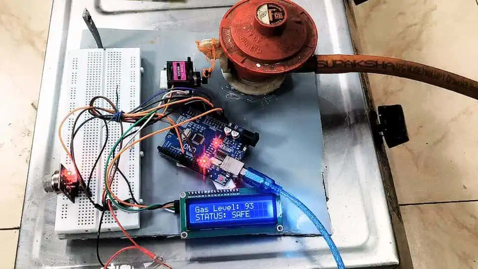
- The Spike: Watch the LCD. It should jump rapidly to 700+.
- Set the Threshold: Set your
dangerThresholdvariable to about 600. This is high enough to ignore cooking smells (onions frying can trigger it if set too low!) but low enough to catch a raw leak.
Troubleshooting: “Why isn’t it working?”
I’ve helped hundreds of students with this lpg gas leakage detector using arduino project. Here are the top 3 issues:
1. The LCD is blank.
- Fix: Check the blue potentiometer on the back of the I2C module. Turn it with a screwdriver until white blocks appear.
2. The Servo buzzes and gets hot.
- Fix: It’s trying to push past its physical limit. If your gas knob hits the “OFF” position at 80 degrees, but you tell the servo to go to 90 degrees, it will keep pushing forever. Change the code
gasValve.write(90)togasValve.write(80).
3. The Sensor value is always 1023 (Max).
- Fix: You wired the connection wrong or the sensor is broken. Also, check the sensitivity screw on the back of the MQ-2 module. If it’s turned all the way up, it thinks everything is gas. Turn it counter-clockwise.
Conclusion: You Just Built a Life Saver
Congratulations. You haven’t just copied code; you’ve built a device that monitors the safety of your home 24/7. You’ve combined analog sensing, digital logic, and mechanical engineering into one compact package.
What’s Next?
This is just Level 1. In my next tutorial, I’ll show you how to swap the Arduino Uno for an ESP8266 so this device can send a WhatsApp message to your phone the second a leak is detected.
Did you build this?
I want to see it! Upload a video of your lpg gas leakage detector in action and tag me. If you have questions, drop them in the comments below—I read every single one.
Stay curious, and keep soldering.