Build Your Own Automatic ON OFF Timer Switch: The “Devraj Lab” Edition (ESP32 + WiFi)
I hate mechanical timer switches.
There, I said it.
I spent years working as an embedded systems engineer, often installing those cheap, plastic analog dials for clients. They needed a simple automatic timer switch for water pump control or to manage their shop’s street lights.
The promise was simple: “Set it and forget it.”
The reality? One power cut, and the clock stops. Suddenly, the street lights are turning on at 2:00 PM in the blazing sun, and the water pump is running dry at midnight, waking up the whole neighborhood.
I knew I could build something better.
After frying a few microcontrollers, battling I2C noise in my workshop, and dealing with the infamous “78:40” Glitch, I finally cracked the code.
Today, I am sharing the full design with source code of the Devraj Lab Smart Timer. It uses an ESP32, features automatic mobile WiFi sync, handles power cuts gracefully, and costs less than a large pizza to build.
If you are looking for a reliable automatic on off timer switch that you can actually trust, this is the build for you.
The “Why”: Real Problems Require Real Engineering
Before we solder a single pin, we must address why most DIY timers fail in the field. It is easy to assume that connecting a microcontroller to a basic relay is enough, but real-world appliances like 1.5HP water pumps or heavy street lights are “inductive loads.”
When these devices are turned off, they fight back by generating a massive spike of voltage, known as Back EMF, which shoots back through the circuit. This electrical noise was the single biggest cause of failure in early prototypes, leading to frozen screens and system crashes.
The Solution: Use a Professional Contactor
To handle heavy inductive loads safely, you must use a 220V AC contactor, such as the Schneider LC1D25M7, or any contactor with a coil voltage that is within the relay module’s operating voltage. If you are building this in the USA, you should use a 110V relay coil contactor instead. This ensures that the high-voltage switching is handled by a rugged component designed for industrial loads, keeping your electronics safe from interference.
Real Project Experience: The “78:40” Glitch
I had just finished installing a prototype for a client. It was controlling a heavy AC motor. The system worked perfectly on my workbench with a small LED bulb.
But the moment I connected the real motor, chaos ensued.
Every time the timer tried to turn the motor OFF, the LCD screen would scramble. Sometimes it went blank. Sometimes it displayed gibberish like “Time: 78:40”.
Why Did This Happen?
It wasn’t a coding bug. It was a physical “lightning strike” on my I2C data lines.
When the relay switches an inductive load (like a pump or street light), it creates a massive Electromagnetic Interference (EMI) spike.
This spike hit the SDA and SCL wires (the communication lines between the ESP32 and the RTC).
The noise was so strong that it literally “tripped” the internal memory of the RTC module. The RTC started feeding the ESP32 scrambled numbers, and the ESP32 just dutifully printed that nonsense to the screen.
The Fix (And Why We Use Capacitors)
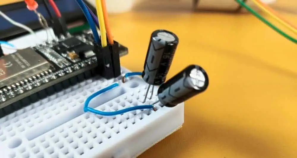
I realized the power rail was dipping and spiking too fast for the ESP32 to handle. I needed a shock absorber.
I didn’t have a large 1000µF capacitor in my bin, but I had a drawer full of smaller ones.
My Solution: I soldered two 470µF capacitors in parallel right next to the ESP32’s 5V input pin.
- Why Parallel? Capacitors in parallel add up. 470µF + 470µF = 940µF. This gave me roughly the 1000µF buffer I needed.
- The Result: The glitch vanished instantly. The power rail became stable, the screen stayed clear, and the timer has been running for months without a single error.
(To ensure maximum reliability, the code includes “Sanity Check” logic that forces the ESP32 to ignore any impossible or unexpected data from the RTC module, keeping the timer running without interruption.)
Why “Devraj Lab Smart Timer” Beats Store-Bought Units
You might be asking, “Devraj, why not just buy a digital timer from Amazon?”
I did the math. Most digital timers in the ₹1,500+ range are decent, but they have fatal flaws. Here is how our custom build compares:
| Feature | Generic Mechanical/Digital Timer | Devraj Lab Smart Timer |
| Price | ₹1,000 – ₹2,500 | ~₹750 |
| Power Cuts | Clock stops or drifts significantly. | RTC Battery keeps time perfect for years. |
| Interface | Tiny, confusing rubber buttons and small icons. | Mobile WiFi Sync & Large LCD Display. |
| Durability | Plastic gears wear out; relay contacts fuse. | Solid State Logic (No gears to break). |
| Repairability | Sealed Unit. If the relay burns, you throw the whole device in the trash. | 100% Modular. If the ₹33 relay fails, you swap it out in 5 minutes. |
The Repairability Factor
This is huge. In India, voltage fluctuations are common. If a spike kills the relay in a store-bought timer, the whole unit is e-waste. With the Devraj Lab design, every part is modular. You are building an asset, not buying a disposable toy.
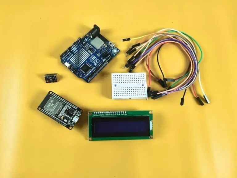
Bill of Materials (BOM): What You Need
I have optimized this list for cost and availability. You don’t need exotic parts. These are standard components available at any local electronics shop or online.
(Prices are estimates based on current market rates in India)
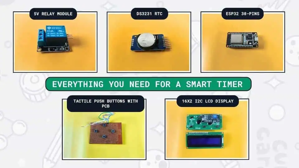
- ESP32 Development Board (30 Pin)
- Cost: ~₹350
- Why: We need WiFi for the mobile sync feature. An Arduino Uno cannot do this easily. The ESP32 is also dual-core, meaning it can handle the WiFi connection without pausing the timer logic.
- I chose the ESP32 for this build because it outperforms traditional boards. If you are new to this, check out my comprehensive microcontroller development boards guide to see how the ESP32 stacks up against the competition.
- DS3231 RTC (Real Time Clock) Module
- Cost: ~₹100
- Why: Do not use the cheaper DS1307. The DS3231 is “Temperature Compensated,” meaning it stays accurate even in hot Indian summers or cold winters. It includes a coin cell battery holder to keep time during power cuts.
- 16×2 I2C LCD Display
- Cost: ~₹180
- Why: The “I2C” version is critical. It uses only 2 wires (SDA and SCL) instead of 16 wires, leaving the other pins free for buttons and relays.
- 1-Channel 5V Relay Module
- Cost: ~₹33
- Why: This module includes the transistor and flyback diode built-in, so you can connect it directly to the ESP32. It can handle up to 10A (roughly 2000 Watts), which is enough for most water pumps and lights.
- 4x Tactile Push Buttons
- Cost: ~₹4
- Why: For manual control (Up, Down, Left, Right). We need a physical interface because you might not always have your phone with you.
- 2x 470µF Electrolytic Capacitors (16V or higher)
- Cost: ~₹10
- Why: Critical. As discussed, these prevent the ESP32 from resetting when the relay clicks. If you have a single 1000µF capacitor, that works too, but two 470µFs in parallel is often cheaper and easier to fit in flat cases.
- Plastic Enclosure & Jumper Wires
- Cost: ~₹80
- Why: Safety first. We are dealing with Mains AC voltage on the relay side. Never leave this project open on a breadboard permanently.
Total Estimated Build Cost: ~₹750
The Circuit Diagram: Keeping It Clean
Wiring is where 90% of beginners make mistakes. If you connect the 5V relay to the 3.3V pin of the ESP32, it won’t trigger. If you swap SDA and SCL, the screen will remain blank.
When wiring your relay and buttons, be careful with the pin numbers. For this project, I used GPIO 23 for the relay. You can refer to my detailed ESP32 pinout reference if you want to use different pins or expand the project further.
Here is the definitive pin mapping for the Devraj Lab Edition.
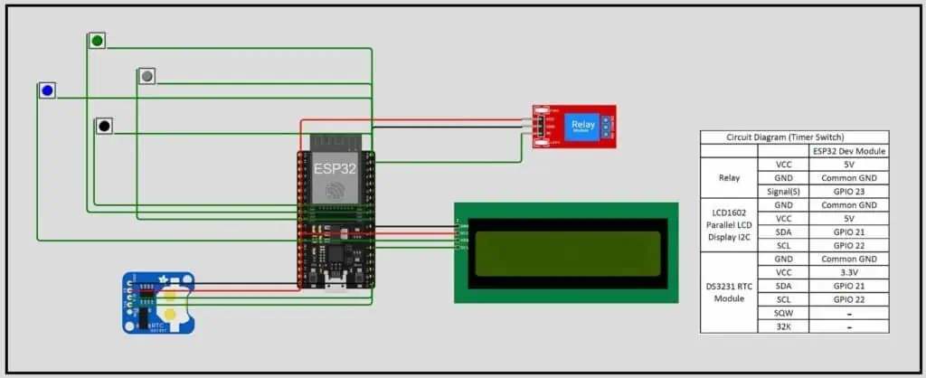
1. Power Distribution (The Most Important Step)
The ESP32 is a 3.3V device, but the Relay and LCD need 5V.
- Input Power: Connect your 5V USB charger or power supply to the VIN pin and GND.
- The Split: From the VIN pin, run wires to the VCC of the Relay and the VCC of the LCD. Do not power these from the ESP32’s 3.3V pin.
2. The I2C Bus (LCD & RTC)
We are using the I2C protocol because it allows us to chain devices.
- SDA (Data): Connect LCD SDA and RTC SDA -> GPIO 21.
- SCL (Clock): Connect LCD SCL and RTC SCL -> GPIO 22.
- Devraj’s Tip: Twist the SDA and SCL wires together. This acts like a “twisted pair” and helps reduce interference from the relay.
3. The Relay (The Muscle)
- Signal Pin: Connect to GPIO 23.
- Why GPIO 23? It is a safe output pin that doesn’t oscillate during boot-up. Some pins on the ESP32 (like GPIO 12) can toggle high/low during startup, which would turn your pump on and off rapidly. GPIO 23 is stable.
4. The Manual Buttons
We use the internal pull-up resistors of the ESP32, so you don’t need external resistors. Just connect one side of the button to the GPIO and the other side to GND.
- UP: GPIO 18
- DOWN: GPIO 19
- LEFT: GPIO 4
- RIGHT: GPIO 5
The Code: Devraj Lab Firmware v2.3.7
This is the brain of the operation. I have refined this code over dozens of iterations to ensure it is robust.
Key Features of v2.3.7:
- WiFi Sync: Creates a hotspot (
Devraj_Smart_Timer). You connect to it, open a page, and click one button to sync the time from your phone. - Non-Blocking Logic: The timer continues to check the schedule even while you are browsing the WiFi menu.
- Auto-Home Safety: If you leave the device in a menu (like “Set Time”), it automatically returns to the main screen after 20 seconds. This ensures the relay logic is never paused indefinitely.
How to Flash the Code
- Open Arduino IDE.
- Install the libraries:
RTClib(by Adafruit) andLiquidCrystal_I2C. - Select Board: ESP32 Dev Module.
- Copy and paste the code below.
(Note: This is the full, refined code based on our latest v2.3.7 release)
C++
#include <Wire.h>
#include <LiquidCrystal_I2C.h>
#include <RTClib.h>
#include <Preferences.h>
#include <WiFi.h>
#include <WebServer.h>

// --- Pin Mapping ---
#define RELAY_PIN 23
#define LED_PIN   2
#define BTN_UP    18
#define BTN_DOWN  19
#define BTN_LEFT  4
#define BTN_RIGHT 5

// --- Objects ---
RTC_DS3231 rtc;
LiquidCrystal_I2C lcd(0x27, 16, 2);
Preferences preferences;
WebServer server(80);

// --- State & Variables ---
enum State { MAIN_SCREEN, SELECT_MENU, SET_CLOCK, SET_ON_TIME, SET_OFF_TIME, RESET_MENU, CONFIRM_SCREEN, FLASH_MSG, WIFI_INFO };
State currentState = MAIN_SCREEN;
State pendingState;

int onH, onM, offH, offM;
int tempH, tempM;
int menuOption = 0, resetOption = 0, editStage = 0, wifiScroll = 0;
bool confirmChoice = true, isOverride = false, backlightOn = true;

unsigned long lastActivity = 0, msgStartTime = 0;
const unsigned long backlightTimeout = 10000;
const unsigned long autoHomeTimeout = 20000;
const unsigned long msgDuration = 2500;

int lastGoodH = 0, lastGoodM = 0;
String flashLine1 = "", flashLine2 = "";

const char* ssid = "Devraj_Smart_Timer";
const char* password = "ofmkdevraj";

void setup() {
  pinMode(RELAY_PIN, OUTPUT); pinMode(LED_PIN, OUTPUT); digitalWrite(RELAY_PIN, LOW);
  pinMode(BTN_UP, INPUT_PULLUP); pinMode(BTN_DOWN, INPUT_PULLUP);
  pinMode(BTN_LEFT, INPUT_PULLUP); pinMode(BTN_RIGHT, INPUT_PULLUP);

  Wire.begin(); lcd.init(); lcd.backlight();

  lcd.setCursor(3, 0); lcd.print("Devraj Lab");
  lcd.setCursor(1, 1); lcd.print("Ph: 8374466801");
  delay(4000);

  WiFi.softAP(ssid, password);
  delay(1000);

  server.on("/", handleRoot);
  server.on("/save", handleSave);
  server.on("/reset", handleWebReset);
  server.on("/sync", handleSync);
  server.begin();

  if (!rtc.begin()) { lcd.print("RTC ERROR!"); while (1); }
  loadPreferences();
  lcd.clear();
  lastActivity = millis();
}

void loop() {
  server.handleClient();
  handleInputs();
  checkTimerLogic();
  updateDisplay();
  manageBacklight();
  manageAutoHome();
  checkFlashTimeout();
}

// --- WEB SERVER FUNCTIONS ---
void handleRoot() {
  DateTime now = rtc.now();
  String s = "<html><head><meta name='viewport' content='width=device-width, initial-scale=1.0'>";
  s += "<style>body{font-family:Arial,sans-serif; text-align:center; background:#f0f0f0; padding:15px;} .card{background:white; padding:15px; border-radius:15px; box-shadow:0 4px 8px rgba(0,0,0,0.1); margin-bottom:15px;} button{padding:15px; font-size:16px; border-radius:10px; border:none; color:white; cursor:pointer;} .btn-full{width:100%;} .btn-blue{background:#007bff;} .btn-red{background:#dc3545;} .btn-orange{background:#fd7e14;} .btn-green{background:#28a745; margin-bottom:10px;}</style>";
  s += "<script>function syncTime(){var d=new Date(); window.location.href='/sync?h='+d.getHours()+'&m='+d.getMinutes()+'&s='+d.getSeconds();}</script></head><body>";
  s += "<h2>Devraj Lab Smart</h2>";
  s += "<div class='card'><b>Status:</b> "+String(isOverride ? "MANUAL" : "AUTOMATIC")+"<br><b>Relay:</b> "+String(digitalRead(RELAY_PIN)?"ON":"OFF")+"</div>";
  s += "<div class='card'><h3>System Clock</h3><button class='btn-green btn-full' onclick='syncTime()'>SYNC MOBILE TIME</button></div>";
  s += "<div class='card'><h3>Update Schedule</h3><form action='/save'>ON: <input type='number' name='onH' value='"+String(onH)+"' style='width:50px'>:<input type='number' name='onM' value='"+String(onM)+"' style='width:50px'><br><br>OFF: <input type='number' name='offH' value='"+String(offH)+"' style='width:50px'>:<input type='number' name='offM' value='"+String(offM)+"' style='width:50px'><br><br><button class='btn-blue btn-full' type='submit'>Save Schedule</button></form></div>";
  s += "<div style='display:flex; justify-content:center;'><a href='/reset?type=mode' style='width:50%;'><button class='btn-orange btn-full'>AUTO/MANUAL</button></a><a href='/reset?type=hard' style='width:50%;'><button class='btn-red btn-full' style='margin-left:5px;'>HARD RESET</button></a></div>";
  s += "</body></html>";
  server.send(200, "text/html", s);
}

void handleSync() {
  if (server.hasArg("h")) {
    rtc.adjust(DateTime(2026, 1, 25, server.arg("h").toInt(), server.arg("m").toInt(), server.arg("s").toInt()));
    currentState = MAIN_SCREEN; // FORCE HOME
    triggerFlash("MOBILE SYNC:", "TIME UPDATED!");
  }
  server.sendHeader("Location", "/"); server.send(302, "text/plain", "");
}

void handleSave() {
  if (server.hasArg("onH")) {
    onH = server.arg("onH").toInt(); onM = server.arg("onM").toInt();
    offH = server.arg("offH").toInt(); offM = server.arg("offM").toInt();
    saveSettings();
    currentState = MAIN_SCREEN; // FORCE HOME
    triggerFlash("WiFi Update:", "Data Stored!");
  }
  server.sendHeader("Location", "/"); server.send(302, "text/plain", "");
}

void handleWebReset() {
  String type = server.arg("type");
  if (type == "hard") {
    rtc.adjust(DateTime(2026, 1, 25, 12, 0, 0)); onH = 17; onM = 30; offH = 6; offM = 15;
    saveSettings();
    currentState = MAIN_SCREEN; // FORCE HOME
    triggerFlash("WiFi Command:", "Hard Reset Done");
  }
  else if (type == "mode") {
    isOverride = !isOverride;
    currentState = MAIN_SCREEN; // FORCE HOME
    triggerFlash("WiFi Command:", isOverride ? "MANUAL" : "AUTOMATIC");
  }
  server.sendHeader("Location", "/"); server.send(302, "text/plain", "");
}

// --- CORE SYSTEM FUNCTIONS ---
void loadPreferences() { preferences.begin("timer-data", false); onH = preferences.getInt("onH", 17); onM = preferences.getInt("onM", 30); offH = preferences.getInt("offH", 6); offM = preferences.getInt("offM", 15); }
void saveSettings() { preferences.putInt("onH", onH); preferences.putInt("onM", onM); preferences.putInt("offH", offH); preferences.putInt("offM", offM); }

void checkTimerLogic() {
  // RELAY PROTECTION: If we are deep in menus, stay in last state
  if (currentState != MAIN_SCREEN && currentState != FLASH_MSG) return;

  DateTime now = rtc.now();
  int h = now.hour(), m = now.minute();
  if (h > 23 || m > 59) { h = lastGoodH; m = lastGoodM; } else { lastGoodH = h; lastGoodM = m; }

  bool relayOn = isOverride;
  if (!isOverride) {
    int cur = h * 60 + m, onT = onH * 60 + onM, offT = offH * 60 + offM;
    if (onT < offT) relayOn = (cur >= onT && cur < offT);
    else relayOn = (cur >= onT || cur < offT);
  }
  digitalWrite(RELAY_PIN, relayOn ? HIGH : LOW);
  digitalWrite(LED_PIN, relayOn ? HIGH : LOW);
}

void handleInputs() {
  static unsigned long lastClick = 0;
  if (millis() - lastClick < 250) return;
  bool bU = !digitalRead(BTN_UP), bD = !digitalRead(BTN_DOWN), bL = !digitalRead(BTN_LEFT), bR = !digitalRead(BTN_RIGHT);
  if (!bU && !bD && !bL && !bR) return;
  lastClick = millis(); wakeDisplay();

  if (currentState == FLASH_MSG) { currentState = MAIN_SCREEN; lcd.clear(); return; }
  if (currentState == WIFI_INFO) {
    if (bL) { currentState = SELECT_MENU; lcd.clear(); }
    else if (bD) { wifiScroll = (wifiScroll + 1) % 3; lcd.clear(); }
    else if (bU) { wifiScroll = (wifiScroll == 0) ? 2 : wifiScroll - 1; lcd.clear(); }
    return;
  }
  if (bU && bD && (currentState == MAIN_SCREEN)) { isOverride = !isOverride; triggerFlash("MODE CHANGED:", isOverride ? "MANUAL" : "AUTOMATIC"); return; }

  switch (currentState) {
    case MAIN_SCREEN:
      if (bR) { currentState = SELECT_MENU; menuOption = 0; lcd.clear(); }
      else if (bU) triggerFlash("SET ON TIME:", timeStr(onH, onM));
      else if (bD) triggerFlash("SET OFF TIME:", timeStr(offH, offM));
      break;
    case SELECT_MENU:
      if (bL) { currentState = MAIN_SCREEN; lcd.clear(); }
      else if (bU) menuOption = (menuOption <= 0) ? 3 : menuOption - 1;
      else if (bD) menuOption = (menuOption >= 3) ? 0 : menuOption + 1;
      else if (bR) {
        if (menuOption == 0) { currentState = SET_CLOCK; editStage = 0; DateTime n = rtc.now(); tempH = n.hour(); tempM = n.minute(); }
        else if (menuOption == 1) { currentState = SET_ON_TIME; editStage = 0; }
        else if (menuOption == 2) { currentState = RESET_MENU; resetOption = 0; }
        else { currentState = WIFI_INFO; wifiScroll = 0; }
        lcd.clear();
      }
      break;
    case RESET_MENU:
      if (bL) { currentState = SELECT_MENU; lcd.clear(); }
      else if (bU || bD) resetOption = !resetOption;
      else if (bR) { pendingState = RESET_MENU; currentState = CONFIRM_SCREEN; confirmChoice = true; }
      break;
    case CONFIRM_SCREEN:
      if (bU || bD) confirmChoice = !confirmChoice;
      else if (bR) {
        if (confirmChoice) {
          if (pendingState == SET_CLOCK) rtc.adjust(DateTime(2026, 1, 25, tempH, tempM, 0));
          else if (pendingState == RESET_MENU) { if (resetOption == 0) { rtc.adjust(DateTime(2026, 1, 25, 12, 0, 0)); onH = 17; onM = 30; offH = 6; offM = 15; } else { onH = 17; onM = 30; offH = 6; offM = 15; } }
          saveSettings(); triggerFlash("SUCCESSFUL!", "DATA STORED");
        } else { currentState = MAIN_SCREEN; lcd.clear(); }
      }
      else if (bL) { currentState = SELECT_MENU; lcd.clear(); }
      break;
    case SET_CLOCK:
    case SET_ON_TIME:
    case SET_OFF_TIME:
      if (bR) { editStage++; if ((currentState == SET_CLOCK && editStage > 1) || (currentState == SET_OFF_TIME && editStage > 1)) { pendingState = currentState; currentState = CONFIRM_SCREEN; confirmChoice = true; } else if (currentState == SET_ON_TIME && editStage > 1) { currentState = SET_OFF_TIME; editStage = 0; } }
      else if (bU) adjustValue(1);
      else if (bD) adjustValue(-1);
      else if (bL) { currentState = SELECT_MENU; lcd.clear(); }
      break;
  }
}

void updateDisplay() {
  static unsigned long lastUpdate = 0;
  if (millis() - lastUpdate < 300) return;
  lastUpdate = millis();
  lcd.setCursor(0,0);
  if (currentState == MAIN_SCREEN) { lcd.printf("TIME: %02d:%02d:%02d  ", lastGoodH, lastGoodM, rtc.now().second()); lcd.setCursor(0,1); lcd.print(isOverride ? "MODE: MANUAL    " : "MODE: AUTOMATIC "); }
  else if (currentState == SELECT_MENU) { lcd.print("SYSTEM MENU:    "); lcd.setCursor(0,1); if(menuOption == 0) lcd.print("> 1. CLOCK SET  "); else if(menuOption == 1) lcd.print("> 2. TIMER SET  "); else if(menuOption == 2) lcd.print("> 3. RESET MENU "); else lcd.print("> 4. WIFI INFO  "); }
  else if (currentState == WIFI_INFO) { if (wifiScroll == 0) { lcd.print("WIFI IP ADDR:   "); lcd.setCursor(0,1); lcd.print("192.168.4.1     "); } else if (wifiScroll == 1) { lcd.print("WIFI NAME (ID): "); lcd.setCursor(0,1); lcd.print("Devraj_Timer    "); } else { lcd.print("WIFI PASSWORD:  "); lcd.setCursor(0,1); lcd.print("ofmkdevraj      "); } }
  else if (currentState == FLASH_MSG) { lcd.print(flashLine1 + "                "); lcd.setCursor(0,1); lcd.print(flashLine2 + "                "); }
  else if (currentState == CONFIRM_SCREEN) { lcd.print("SAVE CHANGES?   "); lcd.setCursor(0,1); lcd.print(confirmChoice ? "> YES [SAVE]    " : "> BACK [CANCEL] "); }
  else if (currentState == RESET_MENU) { lcd.print("CHOOSE RESET:   "); lcd.setCursor(0,1); lcd.print(resetOption == 0 ? "> HARD RESET    " : "> SETTING RESET "); }
  else {
    if(currentState == SET_CLOCK) lcd.print("EDIT CLOCK:     "); else if(currentState == SET_ON_TIME) lcd.print("EDIT ON TIME:   "); else lcd.print("EDIT OFF TIME:  ");
    int h = (currentState == SET_CLOCK) ? tempH : (currentState == SET_ON_TIME ? onH : offH), m = (currentState == SET_CLOCK) ? tempM : (currentState == SET_ON_TIME ? onM : offM);
    lcd.setCursor(0,1); lcd.printf("> %02d:%02d  [%s]", h, m, editStage == 0 ? "HOUR" : "MIN ");
  }
}

void triggerFlash(String l1, String l2) { flashLine1 = l1; flashLine2 = l2; msgStartTime = millis(); currentState = FLASH_MSG; lcd.clear(); }
void checkFlashTimeout() { if (currentState == FLASH_MSG && (millis() - msgStartTime > msgDuration)) { currentState = MAIN_SCREEN; lcd.clear(); } }
String timeStr(int h, int m) { char buf[6]; sprintf(buf, "%02d:%02d", h, m); return String(buf); }
void adjustValue(int dir) { if (currentState == SET_CLOCK) { if(editStage==0) tempH=(tempH+dir+24)%24; else tempM=(tempM+dir+60)%60; } else if (currentState == SET_ON_TIME) { if(editStage==0) onH=(onH+dir+24)%24; else onM=(onM+dir+60)%60; } else if (currentState == SET_OFF_TIME) { if(editStage==0) offH=(offH+dir+24)%24; else offM=(offM+dir+60)%60; } }
void wakeDisplay() { backlightOn = true; lcd.backlight(); lastActivity = millis(); }
void manageBacklight() { if (backlightOn && (millis() - lastActivity > backlightTimeout)) { lcd.noBacklight(); backlightOn = false; } }
void manageAutoHome() { if (currentState != MAIN_SCREEN && (millis() - lastActivity > autoHomeTimeout)) { currentState = MAIN_SCREEN; lcd.clear(); } }
Understanding the Logic (For the Geeks)
1. The “State Machine”
Notice I didn’t use delay(1000) inside the loop. Using delay() stops the processor. If the processor stops, it can’t check if you pressed a button or if the WiFi is trying to connect.
Instead, I used a State Machine. The code is always in one “State” (like MAIN_SCREEN or SET_CLOCK). The loop() runs thousands of times per second, checking “Is a button pressed?” or “Is it time to switch the relay?”
2. The Mobile Sync Magic
How does the phone sync work without typing numbers?
It uses JavaScript running on your phone’s browser.
JavaScript
function syncTime(){
  var d = new Date();
  window.location.href='/sync?h='+d.getHours()+'&m='+d.getMinutes()+'&s='+d.getSeconds();
}
When you click the green button on the web page, this script grabs the exact time from your phone’s system clock and shoots it to the ESP32 in a millisecond URL request. The ESP32 catches this and updates the DS3231 RTC instantly.
User Manual: How to Operate Your Timer
I designed the interface to be intuitive. You don’t need a PhD to turn on your water pump.
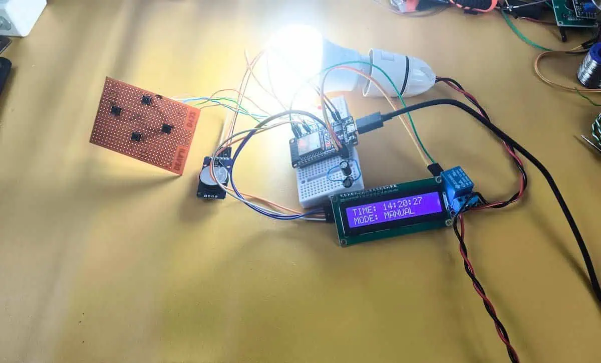
1. The Main Screen
This is the default view.
- Top Line: Shows the current Time (HH:MM:SS).
- Bottom Line: Shows the Mode (
AUTOorMANUAL). - Relay Status: An LED (or icon) indicates if the load is ON.
2. Switching Modes (Auto vs. Manual)
Sometimes you need to run the pump right now, outside of the schedule.
- Action: Hold UP and DOWN together for 1 second.
- Result: The mode toggles.
- MANUAL: The timer logic is disabled. You can turn the relay ON/OFF using the LEFT button.
- AUTOMATIC: The timer follows your scheduled Start and Stop times.
3. Setting the Schedule (The Old Way)
- Press RIGHT to enter the Menu.
- Select 2. TIMER SET.
- Use UP/DOWN to change hours/minutes and RIGHT to confirm.
4. Setting the Schedule (The Smart Way)
This is the “Devraj Lab” special feature.
- On your phone, connect to WiFi:
Devraj_Smart_Timer. - Enter Password:
ofmkdevraj. - Open browser and go to:
192.168.4.1. - Click the big GREEN BUTTON to sync time.
- Type your ON and OFF times and click SAVE.
Troubleshooting: What if it doesn’t work?
Even the best engineering can have hiccups. Here is how to fix common issues.
Issue 1: The screen shows weird symbols or “78:40” when the pump turns off.
- Cause: Back EMF from the motor is resetting the LCD controller.
- Fix: Check your capacitors! Ensure the two 470µF capacitors are soldered securely and close to the ESP32/LCD power pins. If the problem persists, move the relay module further away from the LCD.
Issue 2: The WiFi connects, but the page won’t load.
- Cause: Your phone might be trying to use Mobile data because the ESP32 has no internet.
- Fix: Turn off “Mobile Data” on your phone for a minute. Or, try a different browser (Chrome works best).
Issue 3: I forgot the WiFi Password.
- Cause: It happens to the best of us.
- Fix: I added a helper menu!
- Press RIGHT to enter the System Menu.
- Scroll down to 4. WIFI INFO.
- Press DOWN to reveal the IP, SSID, and Password on the screen.
Enclosure & Final Assembly
Don’t leave this beautiful project naked on a table.
- The Box: Use a generic 4×4 inch PVC electrical junction box (available at any hardware store for ₹50).
- The Cutouts: Use a Dremel or a hot knife to cut a rectangle for the LCD. Drill 4 holes for the push buttons.
- Mounting: Use hot glue to secure the ESP32 and Relay. Ensure the back of the PCB doesn’t touch anything metal!
Conclusion
We started with a frustration—unreliable mechanical timers that failed us when we needed them most.
We ended with a robust, WiFi-enabled Smart Timer that:
- Keeps perfect time (thanks to DS3231).
- Withstands electrical noise (thanks to our capacitor shock absorbers).
- Syncs effortlessly with your phone.
- Is fully repairable and modular.
By adding WiFi connectivity to a standard timer, we are turning a simple tool into a smart device. This is a perfect example of what IoT means—connecting physical hardware to the internet to solve real-world problems.
This is the difference between “sticking components together” and Engineering.
If you build this Devraj Lab Smart Timer, please share your photos in the comments below. Did you use it for a water pump? A hydroponic setup? Let me know!
Happy Making!