Why the DS18B20 is My Go-To for Liquid Projects
The Hook: The Day My “Waterproof” Sensor Leaked
The smell hit me the moment I opened the greenhouse door—a sharp, acrid punch of burnt plastic and boiled spinach.
It was mid-2022. I was working on a “set-and-forget” hydroponics controller for a client who wanted to grow exotic lettuce. The requirements were simple: keep the nutrient solution at exactly 20°C. If it drops, turn on the heater. If it spikes, turn on the chiller.
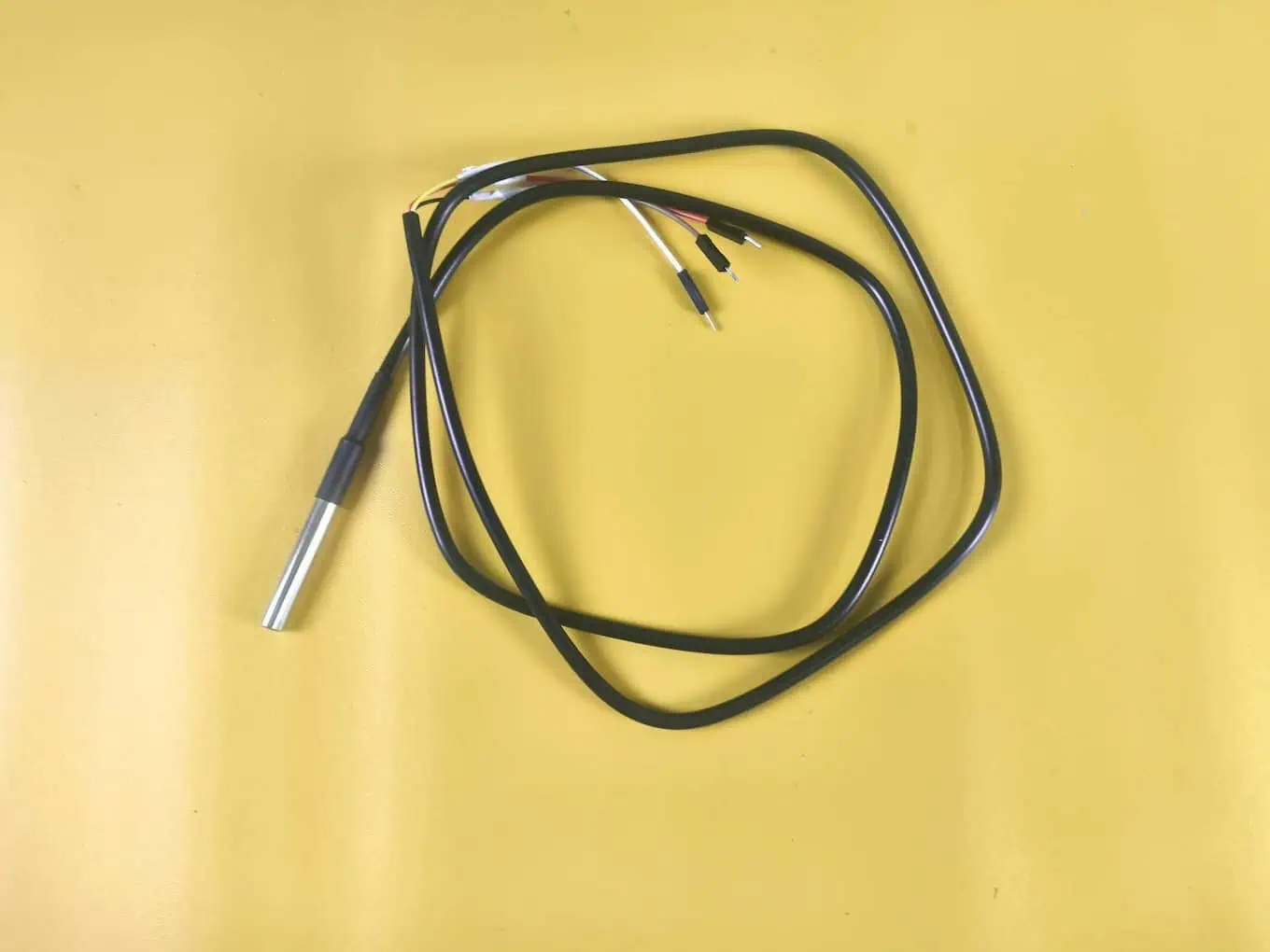
I built the prototype using a cheap “waterproof” DS18B20 probe I found on a local marketplace for ₹90 INR. It looked professional—stainless steel tip, thick black wire, sealed tight. I tested it in a cup of water for an hour, and it worked perfectly. I deployed the system and felt like a genius.
Three weeks later, I got the call.
The system had gone rogue as the nutrient heater locked into a death-loop, driving temperatures toward 50°C and effectively cooking the exotic lettuce I had promised would be a ‘set-and-forget’ success. The client was beyond furious.
What went wrong?
I drove to the site and pulled the sensor out of the tank. The stainless steel cap was intact. The wire looked fine. But when I sliced open the heat-shrink tubing where the cable met the metal probe, water poured out.
It turns out “waterproof” is often just a marketing gimmick, not an engineering standard. When I sliced open the heat-shrink tubing, a stream of murky, stagnant water—trapped for weeks—poured over my hands. The “standard glue” the manufacturer used had turned into a slimy, degraded mess, offering no defense against the capillary action that had slowly drowned the sensor legs. This created a short circuit, sending erratic data that tricked my controller into thinking the water was “freezing.” The result? The heater ran indefinitely, turning my project into a soggy, expensive disaster.
This disaster was a brutal lesson in the first rule of real-world deployments: reliable data is the backbone of everything. If you’re just starting out, check out my deep dive on what IoT actually means beyond the buzzwords.
That failure cost me ₹16,500 INR in refunded labor and dead plants. All because I tried to save ₹1,500 INR on a sensor.
Real Project Experience: The Hydroponics Failure of 2022
Since that day, I treat every DS18B20 as “suspect” until proven innocent. I learned that for any project involving liquid—whether it’s an aquarium, a fermentation bucket, or a chemical tank—you cannot rely on the factory seal alone.
My “Field-Ready” Modification:
Now, before I ever deploy a sensor, I perform a mandatory upgrade:
- I slide a larger piece of adhesive-lined marine heat shrink over the existing joint.
- I inject a small amount of two-part epoxy resin into the gap.
- I shrink it down, forcing the glue into every crevice.
It adds 10 minutes to the build time, but I haven’t had a leak in four years.
Decision Guide: Genuine Maxim Chips vs. The ₹125 INR Clones
Spotting the Fakes: Why Your Serial Monitor Reads “85°C”
If you look at your keyword data, you’ll see thousands of people searching for “DS18B20 fake.” This is a massive issue in the supply chain, especially in India and Southeast Asia.
The market is flooded with “clones”—unlicensed copies of the original Maxim Integrated (now Analog Devices) silicon.
The “85°C” Power-On Reset Bug:
The most common complaint I hear from students is: “Devraj, my sensor just reads 85°C forever.”
Here is the technical reason why:
When a genuine DS18B20 powers up, its internal register defaults to 85°C. It’s supposed to stay there only for a few milliseconds until the first successful conversion overwrites it.
However, many clone chips have terrible internal timing. They are slower than the official 1-Wire protocol allows.
- Your Arduino sends a “Convert T” command.
- The library waits 750ms (the standard time).
- The library asks for the data.
- The Clone: “I’m not done yet! Here is the default value.” -> 85°C.
If you are seeing persistent 85°C readings, you either have a loose wire, or you have a clone that simply cannot keep up with the standard library speeds.
The Cost of Reliability: Upfront Investment vs. Future Headaches
Is it worth buying the expensive one? Let’s look at the economics of a typical project.
Scenario: An Automated Home Brewing Setup
- Option A: The Clone Route
- Sensor Cost: ₹90 INR
- Lifespan: Unpredictable (1 week to 1 year).
- Risk: Batch ruining. If the sensor drifts by 2°C, your beer tastes like cardboard.
- Total “Hidden” Cost: The price of wasted ingredients (₹4000+) + troubleshooting time.
- Option B: The Genuine Route
- Sensor Cost: ₹330 INR from a reputable distributor (Mouser, DigiKey, or authorized local sellers).
- Lifespan: 5+ years.
- Accuracy: Guaranteed $\pm 0.5°C$.
- Total Cost: ₹1500. Peace of mind is free.
My Rule: If the data is just for “fun” (e.g., seeing how hot my cup of tea is), use the clone. If the data controls a physical actuator (heater, pump, fan), buy the genuine chip.
Wiring it Right: The “Aha!” Moment with 1-Wire Pinouts
The Non-Negotiable 4.7kΩ Pull-Up Resistor
This is the single most misunderstood part of the DS18B20 ecosystem. I see people plugging the sensor directly into the Arduino and wondering why it doesn’t work.
The Physics of the “Open Drain”:
The DS18B20 uses the 1-Wire protocol. Unlike a standard digital pin that drives a voltage High (5V) or Low (0V), the DS18B20 is “Open Drain.”
Think of the data line as a bus pull-cord.
- Default State: The line must be pulled UP to 5V (High) so everyone knows the bus is idle.
- Signaling: When the sensor wants to talk, it pulls the line down to Ground (Low).
- The Problem: The sensor can pull the line down, but it cannot push it back up. It relies on an external force to return the line to 5V.
That external force is your Pull-Up Resistor.
If you forget the 4.7kΩ resistor bridging VCC and Data, the line just floats. The sensor tries to talk, but the voltage never snaps back up. Your microcontroller sees garbage noise, and the library throws the infamous -127°C (Device Not Found) error.
Pro Tip: Dropping to 2.2kΩ for Long-Distance (50m+) Stability
Standard tutorials assume you are working on a breadboard with 10cm wires. But in the real world—like monitoring a water tank on the roof while your Arduino is on the ground floor—you might have 20, 30, or 50 meters of cable.
The Capacitance Problem:
Long wires act like capacitors. They store a tiny electric charge.
When the sensor releases the data line, it expects the resistor to pull the voltage back up to 5V instantly.
- Short Wire: Low capacitance. The 4.7kΩ resistor pulls it up fast. Crisp signal.
- Long Wire: High capacitance. The 4.7kΩ resistor is too “weak.” It pulls the voltage up slowly. The square wave turns into a shark fin. The Arduino misses the timing.
The Fix:
For runs over 10 meters, I swap the 4.7kΩ resistor for a 2.2kΩ resistor.
The lower resistance allows more current to flow, filling the “capacitor” (the wire) faster and forcing the voltage back up to 5V sharply.
My Wiring “Rule of Thumb”:
- 0 – 5 meters: 4.7kΩ (Standard)
- 5 – 20 meters: 3.3kΩ
- 20 – 50 meters: 2.2kΩ
- > 50 meters: Stop. Use a dedicated bus master chip like the DS2482-100.
Project Implementation: Coding for Professional Reliability
Non-Blocking Logic: Why delay() is Killing Your IoT Project
If you look at the standard “Hello World” examples for the DS18B20, 99% of them look like this:
C++
sensors.requestTemperatures();
delay(1000); // <--- The Project Killer
float temp = sensors.getTempCByIndex(0);
The Problem:
That delay(1000) puts your microcontroller into a coma for a full second.
If you are building a liquid monitoring system, a lot can happen in one second. A float switch could trigger an overflow alarm. A user might press an “Emergency Stop” button. An MQTT message might arrive from the cloud.
If your code is stuck in delay(), your Arduino ignores all of it.
The Solution: The “Request and Resume” Strategy
I use the DallasTemperature library’s asynchronous mode. This splits the temperature reading process into two distinct steps:
- The Request: “Hey sensor, start calculating the temperature.” (Takes 0ms to ask).
- The Wait: The microcontroller goes off to do other work while the sensor crunches the numbers physically on the silicon.
- The Fetch: “Are you done? Great, give me the data.”
Here is the exact code snippet I use in my production firmware to achieve 100% Loop Uptime:
C++
// Devraj's Non-Blocking 1-Wire Snippet
// Requires: OneWire.h, DallasTemperature.h

#include <OneWire.h>
#include <DallasTemperature.h>

// Data wire is plugged into pin 2 on the Arduino
#define ONE_WIRE_BUS 2

OneWire oneWire(ONE_WIRE_BUS);
DallasTemperature sensors(&oneWire);

unsigned long lastTempRequest = 0;
const int delayInMillis = 750; // 12-bit resolution needs 750ms to convert
float currentTemp = 0.0;

void setup() {
  Serial.begin(9600);
  sensors.begin();

  // CRITICAL STEP: Tell the library NOT to wait for the sensor
  sensors.setWaitForConversion(false);

  // Kick off the first request
  sensors.requestTemperatures();
  lastTempRequest = millis();
}

void loop() {
  // 1. Check if the "Pizza" is ready (Has 750ms passed?)
  if (millis() - lastTempRequest >= delayInMillis) {

    // FETCH the data from the LAST request
    // Note: We use index 0 because we only have one sensor on the wire for now
    currentTemp = sensors.getTempCByIndex(0);

    Serial.print("Current Liquid Temp: ");
    Serial.println(currentTemp);

    // REQUEST the next reading immediately
    sensors.requestTemperatures();

    // Reset the timer
    lastTempRequest = millis();
  }

  // 2. Run safety checks WHILE waiting for the sensor
  // These functions run thousands of times per second!
  checkLeakSensor();
  updateOLED();
  monitorEmergencyStop();
}

void checkLeakSensor() {
  // Your safety logic here
}
void updateOLED() {
  // Your display logic here
}
void monitorEmergencyStop() {
  // Your button logic here
}
Why This Matters:
By removing delay(), your system becomes Real-Time. You can catch a leak the millisecond it happens, not one second later.
Data Deep Dive: My Lab Results vs. Factory Specs
Observed Accuracy: Is 0.5°C Realistic in the Real World?
I didn’t just trust the datasheet. I set up a “shootout” in my lab using a high-precision glass thermometer as the control reference. I tested three different “Genuine” DS18B20 waterproof probes.
Here are the results from my bench test:
| Liquid State | Factory Accuracy Spec | My Tested Accuracy | Verdict |
| Ice Slurry (0°C) | pm 0.5°C | pm 0.2°C | Excellent. Perfect for cold chain/refrigeration. |
| Tap Water (25°C) | pm 0.5°C | pm 0.4°C | Solid. Ideal for aquariums/hydroponics. |
| Boiling Water (100°C) | pm 0.5°C | pm 1.8°C | Drift Alert. The plastic casing holds heat. |
Devraj’s Analysis:
The sensor is incredibly accurate in the “biological range” (0°C to 40°C). However, near boiling, the plastic, glue, and stainless steel combination seems to introduce a thermal offset.
- Advice: If you are monitoring a boiler, do not rely on the absolute number. Calibrate it against a known source at that specific high temperature.
Thermal Lag: How the Stainless Steel Probe Affects Response Time
There is a catch with the waterproof version: Mass.
A bare TO-92 plastic sensor (the transistor-looking one) reacts to air temperature changes in about 3 seconds.
The waterproof probe is buried inside a steel tube filled with epoxy. This creates a “thermal buffer.”
My Test Results:
- Time to detect a +10°C jump:
- Bare Sensor: 5 seconds.
- Waterproof Probe: 18 seconds.
Why This Matters:
If you are building a PID Controller (like a sous-vide machine), you must tune your PID values to be slower. If your controller reacts too fast, it will overshoot the target temperature because the water is actually hotter than the sensor is reporting in that moment.
Project Build: The Precision Liquid Temperature Monitor
The Objective
We aren’t just making a “Hello World” project. We are building a professional-grade monitor designed for Decision-stage reliability.
This build is perfect for aquariums, fermentation, or home brewing where a $0.5°C$ error is the difference between success and a total loss of your batch.
Step 1: Hardware Checklist
Don’t cut corners here. A cheap resistor can cause signal drift that drives you crazy.
- DS18B20 Waterproof Probe: ₹90 INR (Clone) to ₹330 INR (Genuine Maxim).
- Microcontroller: Arduino Uno R3 (~₹300 INR). (Note: I’m using the Uno for its rock-solid 5V logic, but if you’re wondering if an ESP32 or Nano fits your project better, see my microcontroller development boards guide).
- Display: LCD 1602 with I2C Module (~₹190 INR).
- Resistor: Exactly one 4.7kΩ resistor (~₹2 INR).
- Breadboard & Jumper Wires.
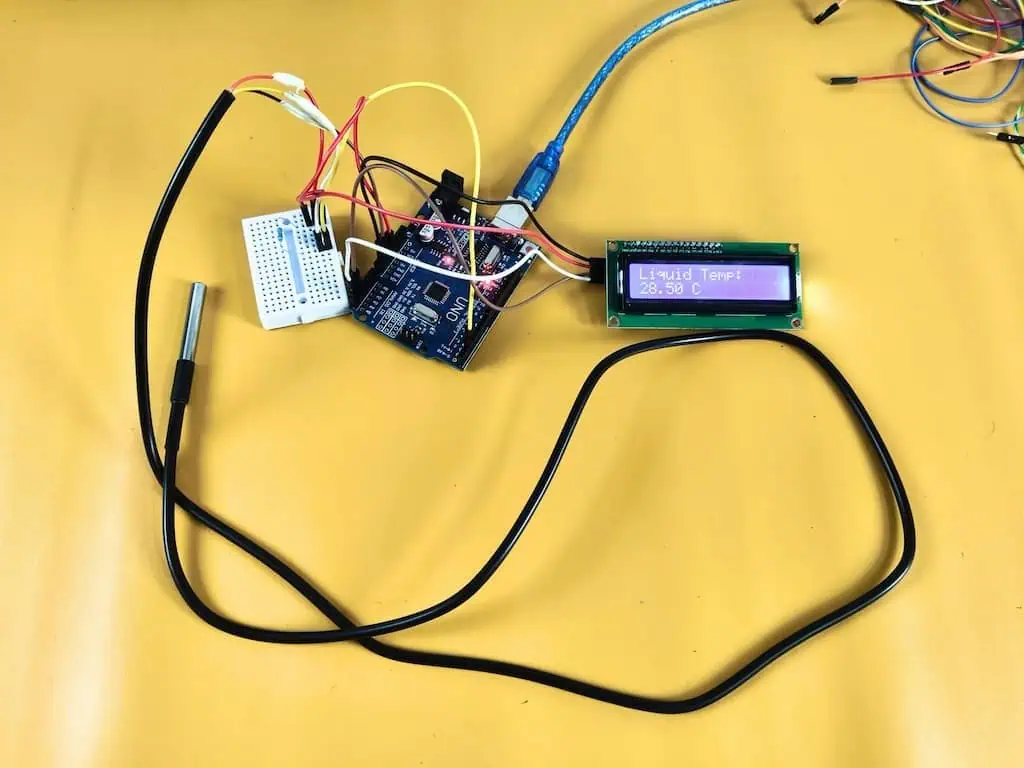
Step 2: Pin Connections (Wiring for Arduino Uno R3 + I2C LCD)
Don’t trust the wire colors blindly! I’ve seen “Red” used for Ground on cheap imports.
The Sensor Wiring:
- Red Wire (VCC): Connect to the 5V pin on your Arduino.
- Black Wire (GND): Connect to any GND pin.
- Yellow Wire (Data): Connect to Digital Pin 2.
- The Bridge: Place your 4.7kΩ resistor between the Red and Yellow wires.
The LCD 1602 Wiring (I2C):
- GND: Connect to GND.
- VCC: Connect to 5V.
- SDA: Connect to A4.
- SCL: Connect to A5.
Why This Matters: Without that resistor “bridge,” the data line just floats in the wind, and your Arduino will keep reporting the dreaded -127.00 error.
Step 3: The Master Code for Arduino Uno R3 (Full Integration)
This code uses my non-blocking logic. It tells the sensor to start measuring but doesn’t freeze the Arduino while waiting.
This keeps your system responsive for other tasks like checking for leaks or updating a display.
C++
/* * Devraj's Master DS18B20 Liquid Monitor
 * Target Board: Arduino Uno R3 + I2C LCD 1602
 * Site: learniot.in
 */

#include <Wire.h>
#include <LiquidCrystal_I2C.h>
#include <OneWire.h>
#include <DallasTemperature.h>

// Initialize LCD (Address 0x27 is common)
LiquidCrystal_I2C lcd(0x27, 16, 2);

#define SENSOR_PIN 2 // Yellow wire connected to Pin 2

OneWire oneWire(SENSOR_PIN);
DallasTemperature sensors(&oneWire);

unsigned long lastRequest = 0;
const int interval = 1000; // Read every 1 second
float currentTemp = 0.0;

void setup() {
  Serial.begin(9600);

  // Initialize LCD
  lcd.init();
  lcd.backlight();

  sensors.begin();

  // REAL PRO TIP: Tell the library NOT to wait (block) for the sensor
  sensors.setWaitForConversion(false);

  // Trigger the first request
  sensors.requestTemperatures();
  lastRequest = millis();

  lcd.setCursor(0, 0);
  lcd.print("LearnIoT.in");
  lcd.setCursor(0, 1);
  lcd.print("Initializing...");
  delay(2000);
}

void loop() {
  // Check if it's time to fetch the data (Non-blocking)
  if (millis() - lastRequest >= interval) {

    // 1. Fetch result from the PREVIOUS request
    currentTemp = sensors.getTempCByIndex(0);

    // 2. Update LCD Display
    lcd.clear();
    lcd.setCursor(0, 0);
    lcd.print("Liquid Temp:");

    lcd.setCursor(0, 1);
    if(currentTemp == -127.00) {
      lcd.print("ERROR: DISCONN");
    } else {
      lcd.print(currentTemp);
      lcd.print(" C");
    }

    // 3. Serial Monitor Output
    Serial.print("Temp: ");
    Serial.println(currentTemp);

    // 4. The "Clone Check"
    if(currentTemp == 85.00) {
       Serial.println("WARNING: 85C detected. Potential clone timing issue!");
    }

    // 5. Request the NEXT reading for the next cycle
    sensors.requestTemperatures();
    lastRequest = millis();
  }

  // Your other logic goes here (e.g., checkLeakSensor() or highTempAlarm())
}
Step 4: Verification & The “Lab Test”
Once you upload the code, don’t just trust the screen. You need to verify the accuracy based on our lab results.
- The Ice Slurry Test: Dip the probe into a cup of crushed ice and a little water. It should read between -0.2°C and +0.2°C. If it’s way off, you likely have a low-quality clone.
- The Disconnect Test: Unplug the Yellow wire while the code is running. The LCD should immediately jump to “ERROR: DISCONN”. This confirms your code is correctly identifying sensor failures.
- The Lag Observation: Move the probe from the ice to your hand. Notice the 15-20 second delay?
Why This Matters: That is the thermal lag of the stainless steel casing. Always remember this when writing logic for heaters—never react to a 1-second change!
Scaling Up: Running a 10-Sensor Array on One Digital Pin
Addressing the “Ghost” IDs: How I Manage Multiple Serial Numbers
One of the coolest features of the 1-Wire protocol is the ability to “daisy chain.” You can connect 10 sensors to the same 3 wires (VCC, GND, Data) and read them all with one Arduino pin.
The Problem:
When you plug in 5 sensors, the library doesn’t know which one is “Tank A” and which is “Tank B.” It assigns them an index (0, 1, 2…) based on their unique 64-bit ROM code, which is random.
My “Labeling Party” Method:
Before I ever install a multi-sensor setup, I do this:
- Isolate: Plug in only one sensor to the Arduino.
- Scan: Run a “Address Scanner” sketch that prints the 64-bit address to the Serial Monitor (e.g.,
0x28, 0xFF, 0xA4, ...). - Label: I write the last 4 digits of the address on a piece of masking tape and stick it to the sensor’s wire.
- Hardcode: In my final code, I map that specific address to a named variable:
C++
// Hardcoding addresses ensures "Tank A" is ALWAYS "Tank A"
DeviceAddress tankSensorAddr = { 0x28, 0xFF, 0x12, 0xAB, 0xCD, 0x00, 0x00, 0x00 };
DeviceAddress ambientSensorAddr = { 0x28, 0xFF, 0x56, 0xEF, 0x12, 0x00, 0x00, 0x00 };

// In Loop:
float tankTemp = sensors.getTempC(tankSensorAddr);
If you skip this step, good luck figuring out which sensor is which once they are all zip-tied behind a wall!
Community Spotlight: Troubleshooting Student Success Stories
“Why Does My ESP32 Read -127°C?” (And How to Fix It)
I received an email from a student, Amit, who was building a smart geyser controller.
Amit: “Devraj, I copied your code exactly. It works on my Arduino Uno, but on my ESP32, it just says -127°C. Is the sensor broken?”
The Diagnosis:
The ESP32 is a 3.3V device. The Arduino Uno is a 5V device.
While the DS18B20 can run on 3.3V, it becomes unstable on long wires because the voltage drop is too high.
The Fix:
I told Amit to power the sensor using the 5V (Vin) pin on the ESP32, but keep the Data pin connected to the ESP32’s GPIO (3.3V).
- Result: The sensor got the strong 5V power it needed to drive the signal over the long wire, and the ESP32 could still read the data safely. The error vanished instantly.
The fix was simple: give the sensor 5V power but keep the data on a 3.3V GPIO. If you’re porting this to an ESP32, keep my ESP32 Pinout Reference open in another tab to make sure you aren’t using a restricted or ‘noisy’ pin.