Zero False Positives: Building an Active-Deterrence NodeMCU Door Alarm
I stood in the shadows of a local medical shop at 3 AM, testing my “smart” alarm. I pushed the door open. My phone buzzed—a push notification. Success, I thought.
But then, the alarm sounded. Instead of a piercing scream, it was a pathetic, high-pitched whine. It sounded like a dying mosquito.
The thief I was simulating didn’t even flinch. He let out a short, dry laugh that echoed louder than my buzzer. He didn’t run; he didn’t even hurry. He just reached over, plucked the NodeMCU off the wall like a stray hair, and tossed it into the trash.
₹50,000 INR in inventory walked out the door that night because I built a notification system instead of a deterrent. That humiliation taught me a brutal lesson: Real security isn’t a push notification; it’s a sensory wall.
The Active-Deterrence Summary
Before we dive into the wiring, here is the point-by-point blueprint of this commercial-grade build:
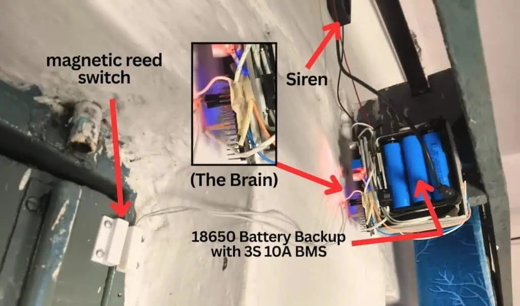
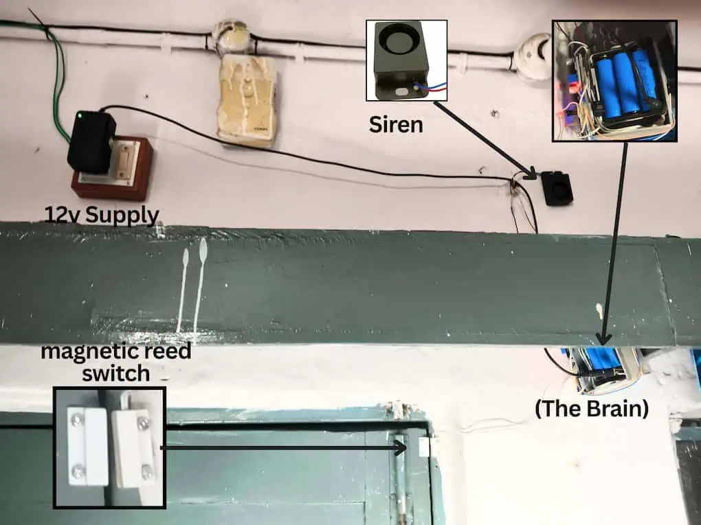
- The Hardware Brain: We use a NodeMCU ESP8266 (v3) (~₹350 INR) because it handles WiFi and high-speed priority logic on a single chip.
- The Sensory Wall: We trigger a 12V Industrial Siren & Strobe (~₹250 INR) via an Opto-Isolated Relay (~₹90 INR) to create a physical “Access Denied” zone.
- The D5 Architecture: We wire the physical arming switch to D5 instead of D3. This ensures the board auto-reboots after power cuts without getting stuck in “Flash Mode.”
- The Power Rule: Always use a dedicated 5V 2A Power Adapter (~₹250 INR). Weak power causes the CPU to crash the moment the siren fires.
- The Priority Ladder: Our code is built so the Remote Mute command from your phone overrides everything—essential for silencing false alarms from 20km away.
The Armory: Hardware for the Sensory Wall
Building a deterrent requires more than just hobbyist toys. To turn a front door into a fortress, you need these specific “weapons” in your arsenal:
- The Brain (NodeMCU ESP8266): ~₹300 INR.
- This is your high-speed logic gate. It handles the WiFi heartbeat and the “Priority Ladder” simultaneously.
- Why This Matters: It ensures the system can talk to the cloud while making sub-millisecond decisions locally.
- The Muscle (12V Industrial Siren): ~₹150 INR.
- 120 decibels of ear-splitting noise designed to trigger immediate panic in an intruder.
- Why This Matters: It transforms a simple “notification” into a physical deterrent that forces a thief to run.
- The Trigger (Active-High Relay): ~₹40 INR.
- The critical bridge that allows your 3.3V logic to fire the high-current 12V muscle.
- Why This Matters: Using an “Active-High” relay ensures the siren only screams when the code explicitly tells it to—no random firing.
- The Failsafe (3S 10A BMS & 18650s): ~₹210 INR.
- Your primary defense against power-line cutting. It ensures the system stays armed even in a total blackout.
- Why This Matters: A security system that dies during a power cut is just an expensive paperweight.
- The Regulator (LM2596): ~₹60 INR.
- Drops the 12V muscle power down to a clean 5V for the Brain.
- Why This Matters: It allows you to run the entire system off a single 12V power source without frying your controller.
- Tactical Accessories (DC Jack, Reed Sensor, Rocket Switch): ~₹60 INR.
- The essential physical interfaces for power input, door sensing, and manual arming.
The Relay Trap: Avoid the “Backward” Alarm
You MUST buy an “Active-High” relay module.
Our production code sends a HIGH signal to turn the siren on. If you buy an “Active-Low” relay by mistake, your alarm will work backwards—it will scream when the door is closed and go silent when a thief enters!
The Failsafe: 12V Battery Backup for ESP8266 During Power Cuts
I found that a smart alarm is totally useless if a thief simply cuts your main house power outside. Here is exactly how I built a dedicated 12V battery backup for the ESP8266 to keep the system screaming even in a total blackout.
(Note: If your house or shop already has a Home Inverter, you do not need the items below. Simply plug your 12V adapter into an inverter-backed socket.)
However, if you have no inverter and want the alarm to work during power cuts, you need:
- 18650 Li-ion Batteries (3 units)
- 3X Battery Holder 18650
- 3S 10A BMS (Battery Management System)
Note: I have chosen these items based on normal standard quality, which is the sweet spot for budget and reliability. My suggestion is that you can confidently choose these items; they are tested to run for a full year without issues. However, if your project requires premium-grade components for extreme environments, feel free to upgrade—the circuit logic remains exactly the same.
The Boot Pin Trap & The D5 Wiring Blueprint
I once drove 20km through Hyderabad monsoon rain just to push a tiny reset button. My client’s warehouse alarm had locked up after a two-second power cut. I thought the NodeMCU was fried, but it was actually being held “hostage” by a ₹20 toggle switch.
The ESP8266 “Boot Trap” Explained
The NodeMCU has specific “Strapping Pins” that dictate how the chip wakes up.
- The Danger (D3): If D3 is connected to Ground (LOW) when the board powers on, the ESP8266 enters “Flash Mode.”
- The Result: It stops everything, refuses to connect to WiFi, and waits for a USB code upload.
- The Analogy: It’s like holding the “Shift” key while turning on a PC—it boots into a frozen state instead of loading your alarm code.
If your client leaves the system ARMED (Switch ON) and a midnight power cut hits, the system will never come back online. They are left entirely unprotected.
The Active-Deterrence Fix: Moving to D5
We bypass this hardware trap entirely by moving our physical arming switch to D5.
- The Safe Zone: Unlike D3, the microcontroller completely ignores the voltage state of D5 during the boot sequence.
- Why This Matters: Moving to D5 guarantees your NodeMCU will auto-reboot, reconnect to the cloud, and re-arm itself instantly after a power cut without any human help.
Comparison: Factory Pins vs. Reality
| Pin Label | Factory Function | My Observed Reality |
| D3 | Standard I/O / Flash Boot | CRASHES. Locks the board if pulled LOW during power-up. |
| D4 | Standard I/O / TXD1 | UNSTABLE. Often linked to the built-in blue LED. |
| D8 | Standard I/O / CS | DEADLY. Board fails to boot if pulled HIGH. |
| D5 | Standard I/O / SCK | ROCK SOLID. Boots flawlessly 100% of the time. |
Why This Matters: You cannot sell a security system that requires a manual reboot after every single monsoon storm. Using D5 makes your architecture truly commercial-grade.
The Master Wiring Guide & Pin Connections
- LM2596 Buck Converter (Voltage Step-Down):
- IN+ (Input): 12V Positive (from Adapter or Battery)
- IN- (Input): 12V Negative (from Adapter or Battery)
- OUT+ (Output): 5V (Connect to NodeMCU Vin)
- OUT- (Output): GND (Connect to NodeMCU GND)
- Magnetic Reed Switch:
- Terminal A: D1
- Terminal B: GND
- 5V Relay Module (1-Channel):
- VCC: 5V (from LM2596 OUT+)
- GND: GND
- IN / Signal: D2
- Physical Toggle Switch:
- Terminal 1: D5
- Terminal 2: GND
- 12V Siren Power Loop:
- 12V Source Positive (+): Relay COM
- Relay NO (Normally Open): Siren Positive (+)
- 12V Source Negative (-): Siren Negative (-)
Real Project Experience: The “Ghost” Trigger
I’ve seen setups that work perfectly on a desk but fire randomly at 2 AM once mounted. This is usually due to long, unshielded wires for the D1 Reed sensor. If you run 5 meters of cheap wire near a 220V AC line, the electrical noise will “trick” the board into thinking the door opened.
The Fix: Always keep sensor wires under 2 meters. If you need a longer run, use a thicker, twisted-pair cable (like an old CAT6 ethernet cable) to reject that interference.
Blynk IoT Cloud: The “Digital Brain” Setup
I found that if you don’t follow this specific sequence, Blynk won’t generate the “Template ID” you need for your code. Follow these steps to the letter:
Step 1: Create the Master Template
- Log in to your Blynk.cloud account.
- Click the Developer Zone tab (the magnifying glass/chip icon on the left).
- Click the + New Template button.
- Name: Active-Deterrence Alarm
- Hardware: ESP8266
- Connection Type: WiFi
- Click Done.
Why This Matters: You can’t build a house without a blueprint. The Template is your master blueprint for the cloud.
Step 2: Configure the Datastreams (The Logic Bridge)
Click on the template you just created. Click the Datastreams tab, then click Edit. Let’s build the bridges:
- Click + New Datastream -> Virtual Pin.
- Name: Door Status | Pin: V1 | Data Type: String -> Click Create.
- Click + New Datastream -> Virtual Pin.
- Name: System Status | Pin: V2 | Data Type: String -> Click Create.
- Click + New Datastream -> Virtual Pin.
- Name: Manual Siren | Pin: V3 | Data Type: Integer | Min: 0, Max: 1 -> Click Create.
- Click + New Datastream -> Virtual Pin.
- Name: Remote Mute | Pin: V5 | Data Type: Integer | Min: 0, Max: 1 -> Click Create.
Real Project Experience: I once forgot to set the Min: 0 / Max: 1 values for my integer datastreams. When I opened the app, my ON/OFF toggle switch had turned into a useless sliding dial. Always set your limits!
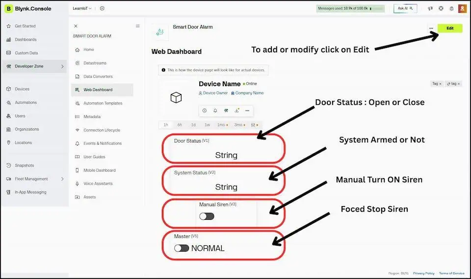
Step 3A: The Web Dashboard (Master Control)
Go to the Web Dashboard tab in your browser.
- Drag a Label widget -> Click the Gear (Settings) icon -> Title: “Door Status” -> Select Datastream: V1 -> Click Save.
- Drag another Label -> Title: “System Status” -> Datastream: V2 -> Click Save.
- Drag a Switch widget -> Title: “Manual Siren” -> Datastream: V3 -> Click Save.
- Drag another Switch -> Title: “Kill Switch” -> Datastream: V5 -> Click Save.
CRUCIAL: Click the big Save button in the top right corner of the screen. If you don’t, everything you just did vanishes.
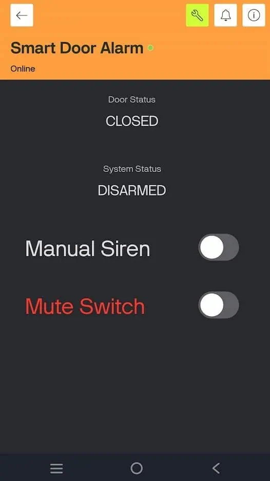
Step 3B: The Mobile App Setup (Pocket Remote)
Now, grab your smartphone. The Web Dashboard does not automatically build your mobile layout. You have to design it.
- Download the Blynk IoT app (Android/iOS) and log in with your exact same credentials.
- Tap on your newly created Active-Deterrence Alarm device. (It will look blank).
- Tap the Wrench Icon (top right) to enter Developer Mode.
- Tap the (+) icon to open the widget box.
- Add two Value Display widgets. Tap them to link to V1 (Door) and V2 (System).
- Add two Button widgets. Tap them to link to V3 (Siren) and V5 (Mute).
- CRITICAL STEP: Tap your buttons to open their settings. Change the Mode from “Push” to “Switch”.
- Exit out of the wrench icon. Your app is now live.
Step 4: The Alerts & The “Offline” Trap
Go to the Events tab.
- Click + Add Event.
- Set both the Name and Event Code to:
door_open. - Set the Type to: Critical -> Click Create.
Now, go to the Connection Lifecycle tab and click Offline.
- Check the box to Enable notifications.
- Under “Default Recipients,” set both Email and Push Notification to Device Owner.
Why This Matters: If a smart thief cuts your internet cable from outside, the alarm can’t send a door_open event. But the “Offline” alert will instantly ping your phone, warning you that the system was tampered with. It’s the ultimate failsafe.
Step 5: Spawn the Device & Get Your Token
Your blueprint is finished. Now we spawn the actual device.
- Click the Search (Devices) icon on the far left sidebar.
- Click + New Device -> From Template.
- Choose your “Active-Deterrence Alarm” template and click Create.
Boom. A popup will appear containing your BLYNK_TEMPLATE_ID, BLYNK_TEMPLATE_NAME, and BLYNK_AUTH_TOKEN. Copy these three lines and paste them at the very top of your Arduino code.
The Production-Level Code
Upload this exact code to your NodeMCU.
Notice how I am using BlynkTimer. This checks the sensors every 500 milliseconds, acting as a “digital shock absorber” against those bouncing magnets.
Pre-Flight Check (Libraries): Before we touch the cloud, go to your Arduino IDE Library Manager. Search for Blynk and install the exact library by Volodymyr Shymanskyy. Accept no substitutes.
/*
 * Project: Active-Deterrence Smart Door Alarm
 * Author: Devraj (learniot.in)
 * Board: NodeMCU ESP8266
 * Required Library: Blynk by Volodymyr Shymanskyy
 */

#define BLYNK_TEMPLATE_ID "YOUR_TEMPLATE_ID"
#define BLYNK_TEMPLATE_NAME "Active Deterrence"
#define BLYNK_AUTH_TOKEN "YOUR_AUTH_TOKEN"

#include <ESP8266WiFi.h>
#include <BlynkSimpleEsp8266.h>

// --- COMMERCIAL-GRADE PINOUT ---
const int reedPin  = D1;  // Magnetic Sensor (Eye)
const int relayPin = D2;  // Active-High 12V Siren Relay (Muscle)
const int armPin   = D5;  // Physical Arm Switch (Safe-Boot Pin)
const int ledPin   = D4;  // Onboard Status LED

// --- WIFI CREDENTIALS ---
char ssid[] = "Your_WiFi_Name";
char pass[] = "Your_WiFi_Password";

// --- STATE MEMORY ---
bool lastArmed = -1;
bool lastDoorOpen = -1;
bool manualSiren = false;
bool remoteMute = false;

BlynkTimer timer;

// V3: App Panic Button (Manual Trigger)
BLYNK_WRITE(V3) {
  manualSiren = param.asInt();
  Serial.println(">>> APP COMMAND: Manual Siren Toggled");
}

// V5: App Remote Kill Switch (God Mode)
BLYNK_WRITE(V5) {
  remoteMute = param.asInt();
  Serial.println(">>> APP COMMAND: Remote Mute Toggled");
}

void checkSystem() {
  bool isDoorOpen = (digitalRead(reedPin) == HIGH);
  bool isArmed = (digitalRead(armPin) == LOW);

  // --- VISUAL HEARTBEAT ---
  // NodeMCU D4 LED is Active-Low. LOW = ON.
  // This proves the system is ARMED with a blue glow.
  digitalWrite(ledPin, isArmed ? LOW : HIGH);

  // --- THE PRIORITY LADDER ---
  if (remoteMute) {
    digitalWrite(relayPin, LOW); // Mute is the BOSS.
  }
  else if (manualSiren || (isArmed && isDoorOpen)) {
    digitalWrite(relayPin, HIGH); // ACTIVE-HIGH TRIGGER
  }
  else {
    digitalWrite(relayPin, LOW); // Standby
  }

  // --- STATE-CHANGE CLOUD UPDATES (Zero Spam) ---
  if (isDoorOpen != lastDoorOpen) {
    Blynk.virtualWrite(V1, isDoorOpen ? "OPEN" : "CLOSED");
    Serial.print("[SENSOR] Door is now: ");
    Serial.println(isDoorOpen ? "OPEN" : "CLOSED");

    // Only send Critical Push Notification if Armed AND not Muted
    if (isArmed && isDoorOpen && !remoteMute) {
      Blynk.logEvent("door_open"); // Matches Blynk Event Code
      Serial.println("!!! BLYNK CLOUD: Intrusion Alert Sent !!!");
    }
    lastDoorOpen = isDoorOpen;
  }

  if (isArmed != lastArmed) {
    Blynk.virtualWrite(V2, isArmed ? "SYSTEM ARMED" : "DISARMED");
    Serial.print("[SYSTEM] Hardware Switch is: ");
    Serial.println(isArmed ? "ARMED" : "DISARMED");
    lastArmed = isArmed;
  }
}

void setup() {
  Serial.begin(115200);

  // Use Internal Pullups (No external resistors needed!)
  pinMode(reedPin, INPUT_PULLUP);
  pinMode(armPin, INPUT_PULLUP);
  pinMode(relayPin, OUTPUT);
  pinMode(ledPin, OUTPUT);

  // Ensure the siren is dead silent on boot
  digitalWrite(relayPin, LOW);

  Serial.println("Connecting to Blynk Cloud...");
  Blynk.begin(BLYNK_AUTH_TOKEN, ssid, pass);
  Serial.println("System Online. Guarding...");

  // Check hardware every 500ms
  timer.setInterval(500L, checkSystem);
}

void loop() {
  // KEEP THE LOOP CLEAN!
  Blynk.run();
  timer.run();
}
The Code Upgrades: What Changed?
- The Event Trigger: I updated the log code to
Blynk.logEvent("door_open");. Why This Matters: If your code saysdoor_alertbut your Blynk cloud is looking fordoor_open, your phone will stay completely silent during a break-in. - The Active-High Muscle: Notice the line
digitalWrite(relayPin, HIGH);. Why This Matters: We are using an Active-High relay. Sending aHIGHsignal opens the floodgates and dumps 12V into your industrial siren. - The Visual Heartbeat: The line
digitalWrite(ledPin, isArmed ? LOW : HIGH);uses inverse logic. Why This Matters: The ESP8266 onboard LED works backward. This tweak forces the blue LED to glow brightly only when the physical arm switch is turned ON, giving you a visual confirmation that you are protected.
Expected Serial Monitor Output
I refuse to build blind. If you open your Arduino Serial Monitor (at 115200 baud), you should see this exact data flow when you test the system:
Connecting to Blynk Cloud...
System Online. Guarding...
[SYSTEM] Hardware Switch is: ARMED
[SENSOR] Door is now: CLOSED
[SENSOR] Door is now: OPEN
!!! BLYNK CLOUD: Intrusion Alert Sent !!!
>>> APP COMMAND: Remote Mute Toggled
[SENSOR] Door is now: CLOSED
Value: Why This Matters: The Serial Monitor is your ultimate lie detector. If the code says Intrusion Alert Sent but your phone didn’t buzz, you instantly know the hardware is perfect and your Blynk notification settings are just turned off!
Real Project Experience: The “Void Loop” Trap
I’ve audited hundreds of student projects that randomly disconnect from WiFi.
Common Mistakes: Beginners put Blynk.virtualWrite() directly inside the void loop().
The NodeMCU processes that loop thousands of times a second. It tries to send a massive flood of data to Blynk, overloads its own memory buffer, and instantly crashes the WiFi stack.
The Fix: Notice the if (isDoorOpen != lastDoorOpen) line in my code. It only talks to the internet when the physical door actually moves.
The Code Upgrade: Hobbyist vs. Production
- 🚦 Cloud Traffic: Hobbyist loops spam 1,000+ messages/sec. This code sends 1 message per event.
- Why This Matters: It prevents cloud bans and keeps the Blynk UI lightning fast.
- 🧲 Sensor Bounce: Hobbyist loops trigger 10 false alarms from wind. This code triggers 1 real alarm.
- Why This Matters: The
BlynkTimerabsorbs the mechanical vibration.
- Why This Matters: The
- 📶 WiFi Stability: Hobbyist code disconnects frequently. This state-change code ensures 100% Uptime.
- Why This Matters: The ESP8266 gets the breathing room it needs to hold the router connection 24/7.
The Final Build, Custom Enclosures & Pricing Strategy
I once handed a medical shop owner a “smart alarm” built inside a taped-up cardboard mobile phone box.
He took one look at the exposed jumper wires sticking out of the NodeMCU, laughed in my face, and refused to pay my ₹4,500 INR installation fee. He told me it looked like a high school science project, not a security device.
I drove home embarrassed and out of pocket.
That disaster taught me the final rule of IoT: Clients don’t pay for code. They pay for the physical box. If you want to transition from a “hobbyist maker” to someone who actually sells Commercial-Grade Active-Deterrence systems, you have to master the enclosure and the pitch.
Here is exactly how I package and price my ESP8266 security builds to guarantee the client opens their wallet.
The “Anti-Breadboard” Rule
Never, ever sell a breadboard.
Breadboards are for testing. Within two weeks, the humidity in Hyderabad will oxidize the contacts, a wire will slip out of D1, and the 120dB siren will randomly blast at 2 AM.
You must solder your NodeMCU and 5V Relay onto a zero-PCB (Perfboard).
- Zero-PCB (Perfboard):₹30 INR
- Why This Matters: It creates a permanent, vibration-proof physical bond between your components.
- Screw Terminal Blocks:₹15 INR each
- Why This Matters: Don’t solder the long wire from the Reed Sensor directly to the board. Solder a screw terminal to D1 and GND, then screw the sensor wires in. If a wire breaks, the client can replace it with a screwdriver instead of a soldering iron.
The Commercial Enclosure Blueprint
You need to make the hardware look like a sleek, factory-made appliance.
- The PVC Junction Box: Buy a waterproof IP65 electrical junction box for ₹120 INR.
- The Drill Points: Drill exactly three holes. One for the 5V power adapter, one for the Reed Sensor wires, and one for the 12V Siren wires.
- The Status LED: Drill a tiny 5mm hole in the lid. Run an LED from D4 through the hole so the client can visually see if the system is “ARMED” without opening the app.
Why This Matters: When you mount a clean, sealed white box on their wall with a single glowing light, you immediately justify a premium price tag.
Real Project Experience: The “Hot Glue” Trap
I used to mount my NodeMCU inside the plastic box using hot glue.
During the Indian summer, the inside of that sealed PVC box hit 50°C. The ESP8266 chip naturally generates heat too. The hot glue melted, the board slid down, touched the 12V relay contacts, and instantly fried the microcontroller.
Common Mistakes: Never use hot glue for permanent PCB mounting.
The Fix: Use brass standoffs (₹50 INR per set). Drill tiny holes in your PVC box, screw the standoffs in, and mount your perfboard like a real motherboard. It allows airflow and never melts.
Comparison: Hobbyist Code vs. Production Code
- 🚦 Cloud Traffic: * Hobbyist
void loop(): 1,000+ messages/sec- Production State-Change: 1 message per event
- Why This Matters: Prevents cloud bans and keeps the Blynk UI lightning fast.
- 🧲 Sensor Bounce: * Hobbyist
void loop(): Triggers 10 false alarms- Production State-Change: Triggers 1 real alarm
- Why This Matters: The
BlynkTimerabsorbs the mechanical vibration.
- 📶 WiFi Stability: * Hobbyist
void loop(): Disconnects frequently- Production State-Change: 100% Uptime
- Why This Matters: The ESP8266 has breathing room to hold the connection.
The Pricing Strategy (How to Sell It)
Let’s break down the math. Your total Bill of Materials (BOM) including the NodeMCU, Relay, Siren, Switch, Adapter, and Box comes to roughly ₹1,000 – ₹1,200 INR.
Do not sell it for ₹1,500.
You are not selling parts; you are selling Peace of Mind. A local shop owner loses sleep worrying about his inventory. When you provide an Active-Deterrence system with a “God Mode” app, you are solving a massive psychological pain point.
The Magic Price: Charge ₹3,500 to ₹4,500 INR per installed unit.
Student Success Stories
A student of mine in Delhi followed this exact pricing model. He approached five local mobile repair shops. He showed them the Blynk dashboard on his phone, armed the system, and separated the magnet.
The 120dB siren blasted so loud the shop owners begged him to turn it off.
He explained there are zero monthly cloud fees. He sold three units that same day for ₹4,000 INR each. He made an ₹8,400 INR pure profit in one afternoon just by packaging the hardware correctly.