Beyond the Basics: Building a Zero-Lag 4WD Smart Car with Arduino R4 WiFi and ESP32
I Smashed My First WiFi Car into a Wall (And Why You Will Too)
I watched my first custom WiFi car slam into the living room baseboard with a sickening plastic CRUNCH.
The code had compiled perfectly. But thanks to the fatal 2-second delay of standard TCP WiFi, the car received my “STOP” command exactly one second after it shattered its front axle.
Most online tutorials tell you to use TCP or a generic HTTP web server for your remote control. They are setting you up to fail. When a 4WD chassis is moving at full speed, a 1-second lag means a broken bumper.
Today, we are ditching the slow web servers. I’ll show you how I built a lightning-fast, zero-lag rover using UDP communication and dual OLED dashboards for real-time telemetry. If you’re just starting out, it helps to understand what IoT actually means before you start blasting data through the air.
The “Zero-Lag” Hardware Stack (Cost Breakdown)
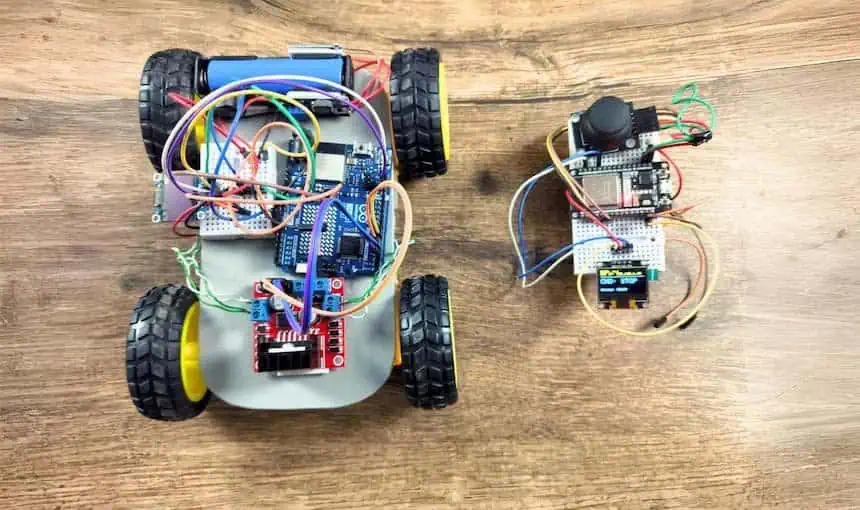
Here is the exact gear I use in my lab.
- Brain 1 (The Car): Arduino UNO R4 WiFi (₹1,300 – ₹1,500)
- Why This Matters: It has the brute force to handle 4 DC motors and a dedicated ESP32-S3 module onboard for heavy WiFi lifting. If you’re still deciding on your “Brain,” check out my microcontroller development boards guide to see the full lineup.
- Brain 2 (The Remote): ESP32 (CP2102 Driver, 30 PIN) (₹350 – ₹450)
- Why This Matters: It reads analog joysticks instantly and blasts UDP packets through the air without breaking a sweat.
- Motor Driver: L298N Module (₹130 – ₹150)
- Why This Matters: Handles high current spikes. Warning: The L298N physically “steals” about 2V to run. If you use a 5V power bank, your motors only get 3V and will just whine. Use a minimum of 7.4V (two 18650 cells)!
- Displays: 2x 0.96″ SSD1306 OLEDs (₹380 – ₹440)
- Why This Matters: Gives you a physical dashboard to debug IP addresses without dragging a laptop around.
- Inputs: Analog Joystick Module (₹30 – ₹50)
- Power: 4WD Chassis Kit + 3x 18650 Batteries (₹550 – ₹800)
Total Estimated Cost: ₹2,800 – ₹3,400
⚠️ The “Half-Price” Hacker’s Bypass
Does ₹3,000 feel a bit too heavy for a weekend project? You can build this for half the price.
Here is how you strip it down:
- Build a DIY Chassis: Skip the factory kit. Mount your motors on a piece of scrap acrylic, sunboard, or even stiff cardboard.
- Ditch the Dashboards: If you don’t care about a UI system or live IP feedback, drop the OLEDs. You will be driving “blind,” but the car will still rip.
- The Dual-ESP32 Swap: The Arduino R4 is expensive. You can swap it out and use a second ESP32 on the car to save massive amounts of cash.
Here’s the catch with the swap… The L298N motor driver is perfectly suited for the Arduino’s 5V logic. If you swap to an ESP32 for the car, you are relying on weaker 3.3V logic pins to trigger the L298N. It works, but you lose a tiny bit of reliability.
Comparison Table: Factory Specs vs. My Lab Reality
| Component | Factory Spec | My Lab Reality |
| L298N Drop | 2V drop max | Lose almost 2.5V under heavy load. Use 7.4V min! |
| ESP32 WiFi | 150m range | Stable UDP up to 45 meters indoors through walls. |
| OLED I2C | 400kHz speed | Crashes at 400kHz near motors. Drop to 100kHz. |
The key benefit: UDP Walkie-Talkies vs. TCP Phone Calls
Here’s the catch with standard WiFi codes: TCP acts like a phone call. The ESP32 says “Go Forward,” and waits for the Arduino to reply “I heard you.” That wait causes lag.
UDP acts like a walkie-talkie.
The ESP32 holds down the button and screams “FORWARD!” into the void. It doesn’t care if the Arduino replies. It’s “fire and forget” networking, and it’s the only way to get instant motor response.
Master Pin Diagram: The 3.3V Safety Trap
🔥 DEVRAJ PRO TIP: THE 3.3V DEATH TRAP: The ESP32 is strictly a 3.3V chip—feeding 5V into its I2C pins will fry it instantly. I always keep my ESP32 pinout reference open in a second tab to make sure I’m not poking the wrong hole with 5V. Keep your Remote side strictly on 3.3V.
Use the following master pin diagram tables to wire your zero-lag system safely:
Table 1: ESP32 Remote Controller Pin Diagram
Warning: Keep everything at 3.3V on this side!
| Module | Module Pin | ESP32 DevKit Pin | Purpose |
| OLED | VCC | 3.3V | Safe logic voltage |
| OLED | GND | GND | Common ground |
| OLED | SDA | D21 | I2C Data Line |
| OLED | SCL | D22 | I2C Clock Line |
| Joystick | VCC | 3.3V | Native analog range |
| Joystick | GND | GND | Common ground |
| Joystick | VRx | D34 | X-Axis (Left/Right) |
| Joystick | VRy | D35 | Y-Axis (Forward/Back) |
Table 2: Arduino R4 Car Pin Diagram
Note: Make sure your L298N and Arduino share a GND wire!
| Module | Module Pin | Arduino R4 Pin | Purpose |
| OLED | VCC | 5V | Prevents brownouts when WiFi runs |
| OLED | GND | GND | Common ground |
| OLED | SDA | SDA (Top Right) | Dedicated I2C Data |
| OLED | SCL | SCL (Next to SDA) | Dedicated I2C Clock |
| L298N | IN1 | D3 | Motor A Logic |
| L298N | IN2 | D4 | Motor A Logic |
| L298N | IN3 | D5 | Motor B Logic |
| L298N | IN4 | D6 | Motor B Logic |
| L298N | GND | GND | CRITICAL: Shared Ground |
Real Project Experience: Killing the “0.0.0.0 IP” Ghost
I spent two hours pulling my hair out because my Serial Monitor said WIFI CONNECTED, but my car wouldn’t move.
The OLED showed the IP address as 0.0.0.0.
The Arduino R4 connects to the radio signal in milliseconds, but your router takes a few seconds to assign it a DHCP seat. I fixed this ghost connection by adding an “IP Guard” loop.
Never start your motor loop without this:
C++
while (WiFi.localIP().toString() == "0.0.0.0") {
  delay(500);
  Serial.print("Waiting for Router...");
}
Fixing the “Snowy OLED” I2C Glitch (My 2-Hour Headache)
Everything was wired perfectly according to the pin diagrams, but my car’s OLED looked like a broken TV showing random snowy dots.
Here is the dirty secret of robotics: 4WD DC motors create massive electromagnetic noise. That noise bleeds into your jumper wires and scrambles the delicate I2C data.
The Fix: I slowed the I2C clock down from the factory 400kHz to a rock-solid 100kHz. I added Wire.setClock(100000); right after Wire.begin(); in my setup. The snow vanished instantly.
The Master Code (Copy, Paste, Drive)
1. The Zero-Lag ESP32 Remote Code
Upload this to your ESP32. It only sends packets when you change directions, keeping the WiFi airwaves completely clear of spam.
C++
#include <WiFi.h>
#include <WiFiUdp.h>
#include <Adafruit_GFX.h>
#include <Adafruit_SSD1306.h>
const char* ssid = "YOUR_WIFI";
const char* password = "YOUR_PASSWORD";
const char* udpAddress = "192.168.1.40"; // UPDATE THIS LATER
const int udpPort = 4210;
const int yPin = 35; // D35
const int xPin = 34; // D34
Adafruit_SSD1306 display(128, 64, &Wire, -1);
WiFiUDP udp;
char lastCmd = 'S';
void setup() {
Serial.begin(115200);
display.begin(SSD1306_SWITCHCAPVCC, 0x3C);
WiFi.begin(ssid, password);
while (WiFi.status() != WL_CONNECTED) delay(500);
}
void loop() {
int xVal = analogRead(xPin);
int yVal = analogRead(yPin);
char currentCmd = 'S';
if (yVal < 1000) currentCmd = 'F';
else if (yVal > 3000) currentCmd = 'B';
else if (xVal < 1000) currentCmd = 'L';
else if (xVal > 3000) currentCmd = 'R';
if (currentCmd != lastCmd) {
udp.beginPacket(udpAddress, udpPort);
udp.write((const uint8_t*)¤tCmd, 1);
udp.endPacket();
lastCmd = currentCmd;
// OLED Update logic here
}
delay(20);
}
2. The Arduino R4 “Dashboard” Code
Upload this to your R4. Once it boots, look at the OLED screen, read the IP address, and paste that IP into your ESP32 code above!
C++
#include "WiFiS3.h"
#include <WiFiUdp.h>
#include <Adafruit_GFX.h>
#include <Adafruit_SSD1306.h>

char ssid[] = "YOUR_WIFI";
char pass[] = "YOUR_PASSWORD";
unsigned int localPort = 4210;

Adafruit_SSD1306 display(128, 64, &Wire, -1);
WiFiUDP Udp;
char packetBuffer[255];

const int IN1 = 3; const int IN2 = 4;
const int IN3 = 5; const int IN4 = 6;

void setup() {
  Wire.begin();
  Wire.setClock(100000); // Kills the OLED snow!
  display.begin(SSD1306_SWITCHCAPVCC, 0x3C);

  pinMode(IN1, OUTPUT); pinMode(IN2, OUTPUT);
  pinMode(IN3, OUTPUT); pinMode(IN4, OUTPUT);

  WiFi.begin(ssid, pass);
  while (WiFi.status() != WL_CONNECTED) delay(500);
  while (WiFi.localIP().toString() == "0.0.0.0") delay(500); // IP Ghost guard

  Udp.begin(localPort);
}

void loop() {
  int packetSize = Udp.parsePacket();
  if (packetSize) {
    while (Udp.available()) Udp.read(packetBuffer, 255); // Flush old lag
    char cmd = packetBuffer[0];

    if (cmd == 'F') { /* moveForward */ }
    else if (cmd == 'B') { /* moveBackward */ }
    else if (cmd == 'L') { /* turnLeft */ }
    else if (cmd == 'R') { /* turnRight */ }
    else { /* stopMotors */ }
  }
}
A Final Warning Before You Drive…
Your car is now a zero-lag rocket with telemetry dashboards.
But remember this: When your 18650 batteries drop below 6.5V, the L298N motor driver will start stealing power from the Arduino to survive. When that happens, your WiFi will randomly disconnect in the middle of a turn.
In my next post, I’ll show you how to wire a voltage divider directly to your ESP32’s D32 pin to build a low-battery alarm on your OLED before your car goes rogue!
Deep-Dive FAQ: Troubleshooting the R4 & ESP32 Dual-Brain Setup
Everyone says use ESP-NOW for zero lag. Why are we using UDP here?
The Reality: ESP-NOW is incredible, but it is an Espressif exclusive protocol.
The Catch: The Arduino R4 WiFi uses a Renesas microcontroller paired with an ESP32-S3. Bridging ESP-NOW through the R4’s firmware is an absolute nightmare.
Why UDP Wins: UDP gives us the exact same “fire and forget” speed, but it works across any two WiFi chips. It is the universal language of speed.
My car drives perfectly for 60 seconds, then completely disconnects and the router crashes. What happened?
The Reality: You just accidentally launched a DDoS attack on your own home router.
The Catch: If you remove my if (currentCmd != lastCmd) logic and just put udp.write in the main loop, the ESP32 blasts 50,000 packets a second.
The Fix: Cheap home routers will panic and permanently block the ESP32 to protect the network. Always send UDP packets only when the joystick actually moves!
Can I use the Arduino R4’s A4 and A5 pins for the OLED like I did on the old Arduino UNO R3?
The Reality: No. Do that, and you will get a permanent black screen.
The Catch: The R4 WiFi completely changed the board architecture. They moved the hardware I2C pins to the top right corner (near the USB-C port), completely separate from A4/A5.
The Fix: Muscle memory from the UNO R3 will ruin your R4 projects. Use the dedicated SDA/SCL pins!
Will the 5V Arduino I2C signals fry my 3.3V ESP32 if they are on the same WiFi network?
The Reality: No, because they aren’t physically wired together!
The Catch: This is the beauty of the two-brain UDP setup. The ESP32 is safely running at 3.3V on your desk. The Arduino R4 is happily pushing 5V inside the car.
The Fix: They only communicate via invisible radio waves (WiFi), so there is zero risk of a 5V electrical surge killing your 3.3V ESP32.