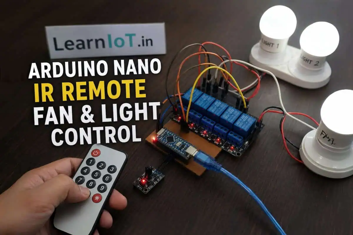
Build a Smart Room with Arduino Nano IR Remote (Fan & Light Control)
It Started with a Simple Problem
I didn’t start this project because I wanted a “smart room.”
I started it because I was annoyed.
Every night, after lying down, I had to get up again just to switch off the light. Then again for the fan. Sometimes, I just stayed under the blanket, avoiding that one extra step — even though I knew it meant wasting electricity.
A simple TV remote—instant, offline, reliable. Why couldn’t my room work the same way?
No apps. No setup. Just press a button and it works.
Because there’s no WiFi involved, the system responds instantly without any delay.
Just a remote — like a TV.
And that’s exactly what this project does.
What You’re Actually Building
This is not just a “relay + Arduino” demo.
You’re building a real, usable system that:
- Controls fan + 2 lights
- Works using a standard IR remote
- Responds instantly (no internet required)
- Can be expanded later (WiFi, automation, etc.)
Final Control System:
| Button | Action |
|---|---|
| Fan button | Toggle fan |
| Light 1 | Toggle |
| Light 2 | Toggle |
* | ALL ON |
# | ALL OFF |
This is not theory — this is something you can actually install in your room.
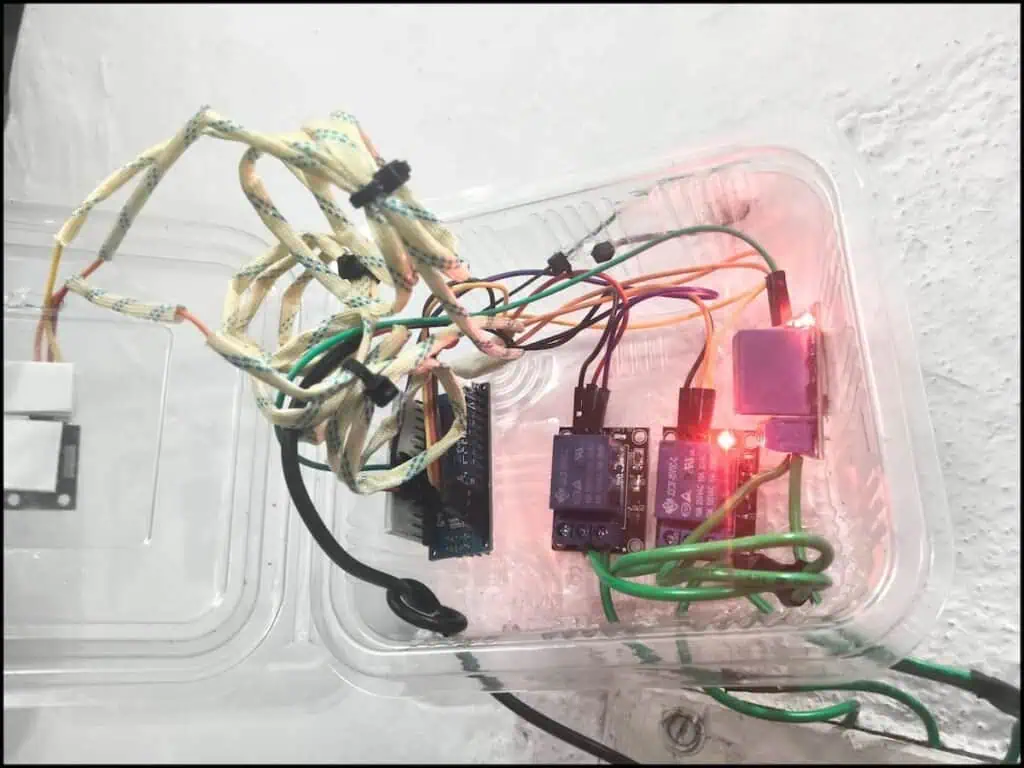
Components Used (Real Setup)
Here’s exactly what I used — nothing fancy:
- Arduino Nano
- IR Receiver Module
- IR Remote
- 3 × 1-Channel Relay Modules
- Jumper Wires
- 5V Power Supply (mobile charger)
No unnecessary components. No over-engineering.
Why I Chose IR Instead of WiFi
Before building, I considered ESP32 and WiFi control.
But here’s the reality:
❌ WiFi Problems
- Delay in switching
- Dependency on internet
- App dependency
- Setup complexity
✅ IR Advantages
- Instant response
- No network required
- Works every time
- Simple to debug
For basic room automation, IR is actually more practical.
How This System Works (Simple Logic)
Let’s break it down without jargon.
- Remote sends IR signal
- IR receiver captures it
- Arduino reads the code
- Based on code → relay ON/OFF
- Relay controls AC load
That’s it.
No cloud. No API. No complexity.
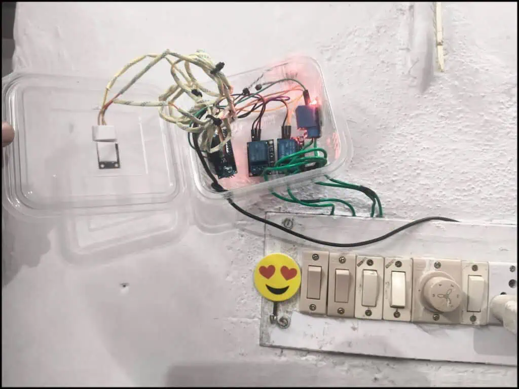
Wiring Setup (Important Part)
🔌 Arduino to IR Receiver
| IR Pin | Arduino |
|---|---|
| VCC | 5V |
| GND | GND |
| OUT | D2 |
🔌 Arduino to Relays
| Relay | Arduino Pin |
|---|---|
| Fan | D3 |
| Light1 | D4 |
| Light2 | D5 |
🔌 Power Supply
Use your 5V charger:
- 5V → Arduino 5V pin
- 5V → Relay VCC
- GND → Common ground
⚡ AC Wiring (Critical)
Think of the relay like a switch controlled by Arduino.
Normally, you press a switch to turn ON a light.
Here, the relay does that job automatically.
Each relay has 3 pins:
- COM → main input wire (Phase)
- NO → goes to your light/fan (OFF by default)
When relay is OFF:
→ COM and NO are not connected → device is OFF
When relay turns ON:
→ COM and NO connect → device turns ON
So basically, relay is just opening and closing a connection like a switch.
Arduino Code (Tested & Working)
This is the exact working code used in this setup:
#include <IRremote.hpp>

#define IR_PIN 2

#define RELAY_FAN     3
#define RELAY_LIGHT1  4
#define RELAY_LIGHT2  5

bool fanState = false;
bool light1State = false;
bool light2State = false;

void setup() {
  Serial.begin(9600);

  pinMode(RELAY_FAN, OUTPUT);
  pinMode(RELAY_LIGHT1, OUTPUT);
  pinMode(RELAY_LIGHT2, OUTPUT);

  // OFF initially (Active HIGH relay → LOW = OFF)
  digitalWrite(RELAY_FAN, LOW);
  digitalWrite(RELAY_LIGHT1, LOW);
  digitalWrite(RELAY_LIGHT2, LOW);

  IrReceiver.begin(IR_PIN, ENABLE_LED_FEEDBACK);

  Serial.println("===== SYSTEM READY =====");
}

void loop() {

  if (IrReceiver.decode()) {

    unsigned long code = IrReceiver.decodedIRData.decodedRawData;

    if (code == 0) {
      IrReceiver.resume();
      return;
    }

    Serial.print("IR Code: ");
    Serial.println(code, HEX);

    switch (code) {

      case 0xBA45FF00:   // Fan toggle
        fanState = !fanState;
        digitalWrite(RELAY_FAN, fanState ? HIGH : LOW);
        Serial.println(fanState ? "Fan ON" : "Fan OFF");
        break;

      case 0xB946FF00:   // Light1 toggle
        light1State = !light1State;
        digitalWrite(RELAY_LIGHT1, light1State ? HIGH : LOW);
        Serial.println(light1State ? "Light1 ON" : "Light1 OFF");
        break;

      case 0xB847FF00:   // Light2 toggle
        light2State = !light2State;
        digitalWrite(RELAY_LIGHT2, light2State ? HIGH : LOW);
        Serial.println(light2State ? "Light2 ON" : "Light2 OFF");
        break;

      case 0xE916FF00:   // * → ALL ON
        fanState = true;
        light1State = true;
        light2State = true;

        digitalWrite(RELAY_FAN, HIGH);
        digitalWrite(RELAY_LIGHT1, HIGH);
        digitalWrite(RELAY_LIGHT2, HIGH);

        Serial.println("* pressed → ALL ON");
        break;

      case 0xF20DFF00:   // # → ALL OFF
        fanState = false;
        light1State = false;
        light2State = false;

        digitalWrite(RELAY_FAN, LOW);
        digitalWrite(RELAY_LIGHT1, LOW);
        digitalWrite(RELAY_LIGHT2, LOW);

        Serial.println("# pressed → ALL OFF");
        break;

      default:
        Serial.println("Other Button");
        break;
    }

    Serial.println("------------------");

    IrReceiver.resume();
  }
}
I uploaded the code expecting everything to work.
Nothing happened.
The IR receiver LED was blinking, but there was no response from the relays.
The Catch I Learned the Hard Way
At first, nothing worked.
The IR receiver LED blinked, but Arduino showed nothing.
Turns out:
- I was using old IRremote code
- But had new library installed
This mismatch silently breaks everything.
👉 Lesson:
Always match code with library version.
Another Mistake (Important)
🔧 Using Active LOW Relay?
If your relay works opposite (turns ON when signal is LOW), then you are using an Active LOW relay.
You don’t need a separate code.
Just change this line:
digitalWrite(RELAY_FAN, fanState ? HIGH : LOW);👉 Replace with:
digitalWrite(RELAY_FAN, fanState ? LOW : HIGH);Apply the same change for all relays.
💡 Quick Test:
Upload this line:
digitalWrite(RELAY_FAN, HIGH);- If relay turns ON → Active HIGH
- If relay stays OFF → Active LOW
Real-World Behavior (What to Expect)
Once the setup is complete, the response feels instant.
Press a button, and the relay switches immediately — no delay, no waiting.
Since everything works offline, the system remains stable and reliable every time you use it.
It doesn’t feel like a DIY project anymore. It behaves like a proper built-in control system.
Common Mistakes You Should Avoid
❌ 1. Powering from Arduino USB
At first, I tried powering the entire setup directly from the Arduino USB.
It worked… but only for a few seconds.
Then the relays started flickering, and sometimes the Arduino would reset randomly.
This happens because the USB port cannot supply enough current for multiple relays.
👉 Use a separate 5V power supply (like a mobile charger) to power both Arduino and relays properly.
❌ 2. Using NC Instead of NO
This is a very common wiring mistake.
If you connect your load to the NC (Normally Closed) terminal, your device will stay ON all the time — even when the relay is OFF.
👉 Always use NO (Normally Open) so the device turns ON only when the relay is activated.
❌ 3. Ignoring Common Ground
One mistake that causes confusing behavior is not connecting all grounds together.
If Arduino, relay module, and power supply don’t share a common ground, the system may behave randomly or not respond at all.
👉 Always connect all GND points together.
❌ 4. Cheap USB Cable
This is something most people overlook.
A cheap or thin USB cable can cause voltage drop, which leads to unstable operation — especially when relays switch.
👉 Use a good-quality USB cable to ensure stable power delivery.
Safety Considerations (Don’t Ignore)
You’re dealing with AC mains here, so this part is not optional.
A loose connection or wrong wiring can heat up within seconds. In the worst case, it can damage components or even cause sparks.
So don’t rush this.
Double-check every connection before powering it ON. Make sure all wires are properly tightened and insulated.
Always test your setup with a simple bulb first before connecting a fan or any heavy load.
And most importantly — never touch the circuit while it’s powered.
Why This Project Matters
This isn’t just a beginner project.
It teaches:
- Real-world control systems
- Signal decoding
- Relay switching
- AC safety
- System debugging
More importantly:
👉 It solves an actual daily problem.
How You Can Upgrade This
Once this works, you can go further:
🔹 Add WiFi Control (ESP32)
If you want to control your devices from your phone, you can replace Arduino Nano with ESP32.
This allows you to build a simple web interface or app-based control while still keeping your relay setup the same.
If you want a more advanced system with mobile control, check my NodeMCU-based smart alarm project.
If you’re confused between boards:
🔗 Microcontroller Development Boards Guide
🔹 Add Fan Speed Control
Right now, the relay only turns the fan ON or OFF.
If you want speed control, you’ll need to use a TRIAC-based dimmer circuit instead of a relay.
This allows you to control fan speed smoothly instead of just switching it.
🔹 Add Motion Sensor
You can add a PIR motion sensor to automate lighting.
This way, lights turn ON when someone enters the room and turn OFF automatically when no motion is detected.
🔹 Save State (EEPROM)
Currently, if power goes OFF, the system resets.
By storing the last state in EEPROM, you can restore the previous ON/OFF status automatically after power returns.
Final Thoughts & What to Do Next
This project taught me something simple but important — most problems don’t need complex solutions.
I initially thought about using WiFi, apps, and cloud control. But in reality, a simple IR remote solved the problem faster, more reliably, and without unnecessary complexity.
The biggest lesson was not in building the circuit, but in debugging it. Library mismatches, relay logic confusion — these small mistakes can completely break a system if you don’t understand what’s happening underneath.
If you’re building this, start simple.
Test it with one relay and a bulb first. Make sure the logic works, understand how your relay behaves (Active HIGH or LOW), and then expand it step by step.
Don’t rush the wiring, especially when dealing with AC. Take your time, verify connections, and prioritize safety.
And once everything is working, you’ll realize — controlling your room with a remote feels natural. Going back to manual switches won’t feel the same.
If you build this or get stuck anywhere, drop a comment. I’ll help you figure it out.