
I Killed a GPIO Pin Building This RC Car (And Six Other Ways It Fought Back)
2.02 volts.
That’s what my multimeter read on a battery pack that, three minutes earlier, my own firmware had confidently reported as “protected.” Not damaged. Not dying. Protected — by a 3-tier safety system I’d built myself, tested myself, and trusted completely.
It wasn’t protected. It was quietly cooking itself while the “safe shutdown” screen sat there looking responsible.
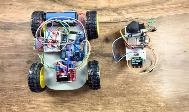
That’s the moment this build stopped being a weekend project and started being an actual argument with physics. Before that: a joystick where forward did nothing and left made the car reverse. After that: a car driving in a permanent circle because one entire side had gone silent — chased through direction pins, PWM pins, an L298N interrogated with a multimeter, and finally a bare Blink sketch that proved one of my ESP8266’s own GPIO pins had simply died.
None of it was exotic. Every single failure was the boring, physical, “why won’t this just work” kind that any RC car build eventually throws at you — which is exactly why it’s worth writing down. This post is the whole build, plus every one of those fights, in the order they actually happened.
If you’ve read my Zero-Lag 4WD UDP car build, think of this as its sibling: same goal — kill remote-control lag — completely different route to get there. That build bridged two different chip families (an Arduino R4’s Renesas core plus an onboard ESP32-S3) over UDP, because getting ESP-NOW to work across that combination is close to a non-starter. This build skips that fight entirely: both boards here are Espressif chips, so ESP-NOW just works, direct — no router, no IP address, no “why is my IP 0.0.0.0” ghost to chase.
Why ESP-NOW instead of WiFi/UDP
Quick comparison, because “just use ESP-NOW, it’s faster” undersells what’s actually different:
| UDP over WiFi (router-based) | ESP-NOW (this build) | |
|---|---|---|
| Needs a router/AP | Yes | No |
| Typical latency | Low, but router-dependent | Very low, direct radio link |
| Works away from home WiFi | No | Yes — works anywhere |
| Cross-vendor (e.g. Arduino R4 + ESP32) | Yes, this is why the UDP build uses it | No — ESP-NOW is Espressif-only |
| Packet delivery guarantee | None (UDP is fire-and-forget) | None by default — this build adds its own CRC16 + sequence numbers + ACK on top |
| Auto-reconnect if boards restart | You handle it yourself | Built into this project’s pairing handshake |
The trade-off is real: because both boards here are Espressif chips (ESP32 + ESP8266), ESP-NOW is available and it’s the simpler, more robust choice for a two-radio link with no infrastructure. If your “car brain” were an Arduino R4 or Uno like the other build, you’d be back to UDP.
The Bill of Materials
Both boards run on 18650 cells in the final build — the remote started life on a single LiPo, briefly detoured through 2×AA (more on why that was a bad idea below), and settled on a single 18650 with a boost converter, which turned out to be the right call for both reliability and proper rechargeable-battery protection. Prices are approximate India retail ranges — always check current listings before ordering.
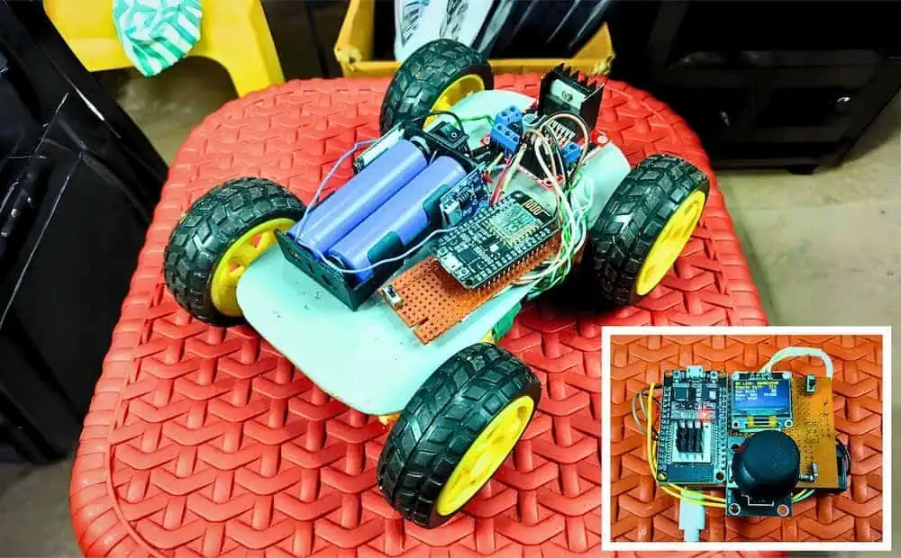
| Part | Role | Approx. Price (India) |
|---|---|---|
| ESP32 DevKit V1 (30-pin, CP2102) | Remote brain | ₹380 – ₹450 |
| ESP8266 NodeMCU (CP2102/CH340) | Car brain | ₹250 – ₹300 |
| L298N motor driver module | Car motor control | ₹130 – ₹150 |
| 0.96″ SSD1306 OLED (I2C) | Remote dashboard | ₹190 – ₹220 |
| Analog joystick module (KY-023 style) | Remote input | ₹30 – ₹50 |
| 4WD chassis kit + 4x BO motors | Car body | ₹450 – ₹650 |
| 3x 18650 Li-ion cells + holders | 1 for remote, 2 for car | ₹230 – ₹380 |
| MT3608 boost converter | Stable 5V for the remote’s single 18650 | ₹25 – ₹40 |
| TP4056 charge module(s) | Optional — onboard charging per cell | ₹15 – ₹30 each |
| Resistors: 100kΩ x3, 33kΩ x1 | Battery-sense dividers | ₹10 – ₹20 total |
| Jumper wires, switches, misc | Wiring | ₹50 – ₹70 |
| Total (approx.) | ₹1,760 – ₹2,360 |
Noticeably cheaper than the R4-based build — no Arduino R4, no second OLED, and ESP8266 undercuts the R4’s price by a fair margin. The trade-off, covered below, is that the L298N was designed with 5V logic in mind, and both these boards run 3.3V logic — it works, but it’s worth knowing going in.
A cheaper alternative I actually tried and don’t recommend: 2×AA alkaline for the remote. It sounds like the obvious “cheap and simple” swap, but it caused more problems than it solved — full story below.
Master Pin Diagram (with voltage domains marked)
This table exists because of a real debugging session late in the build — after switching the remote’s power source, I started seeing flaky behavior that looked like a voltage problem but was actually a grounding problem. Getting the full picture down in one place, with every voltage domain marked, would’ve saved me that detour.
Table 1 — ESP32 Remote
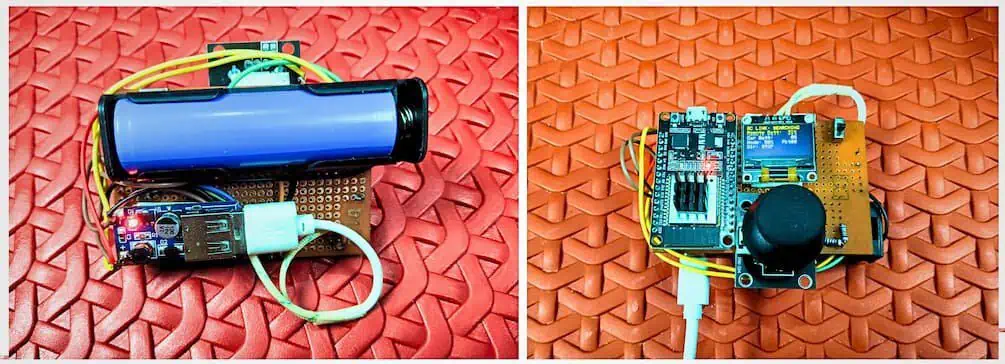
Power chain
18650 (+) → MT3608 IN+ · 18650 (−) → MT3608 IN− · MT3608 OUT+ (trimmed to 5V) → ESP32 VIN · MT3608 OUT− → ESP32 GND
| # | From | To | Voltage / Type |
|---|---|---|---|
| 1 | 18650 (+) | MT3608 IN+ | Raw battery, ~3.0–4.2V |
| 2 | 18650 (−) | MT3608 IN− | GND |
| 3 | MT3608 OUT+ | ESP32 5V/VIN | 5V (trim the onboard pot until this measures exactly 5V) |
| 4 | MT3608 OUT− | ESP32 GND | GND |
| 5 | Joystick VCC | ESP32 3.3V | 3.3V — never 5V |
| 6 | Joystick GND | ESP32 GND | GND |
| 7 | Joystick VRX | ESP32 GPIO35 | Steering axis (analog in) |
| 8 | Joystick VRY | ESP32 GPIO34 | Throttle axis (analog in) |
| 9 | Joystick SW | ESP32 GPIO32 | Mode/E-stop button |
| 10 | OLED VCC | ESP32 3.3V | 3.3V — never 5V |
| 11 | OLED GND | ESP32 GND | GND |
| 12 | OLED SDA | ESP32 GPIO21 | I2C data |
| 13 | OLED SCL | ESP32 GPIO22 | I2C clock |
| 14 | Battery-sense: 18650 (+) | 100kΩ → node → 100kΩ → GND | Tap the raw 18650 terminal, before the MT3608 |
| 15 | Divider midpoint | ESP32 GPIO33 | Battery ADC |
Table 2 — ESP8266 Car
Power chain: 2x18650 (+) → L298N 12V IN · 2x18650 (−) → L298N GND · L298N 5V OUT → NodeMCU VIN · L298N GND → NodeMCU GND
| # | From | To | Voltage / Type |
|---|---|---|---|
| 1 | 2×18650 pack (+) | L298N 12V input | Raw pack, ~6.4–8.4V |
| 2 | 2×18650 pack (−) | L298N GND | GND |
| 3 | L298N 5V OUT (onboard reg.) | NodeMCU VIN | 5V |
| 4 | L298N GND | NodeMCU GND | GND — critical shared ground |
| 5 | L298N IN1 | NodeMCU D1 (GPIO5) | Left dir A |
| 6 | L298N IN2 | NodeMCU D2 (GPIO4) | Left dir B |
| 7 | L298N IN3 | NodeMCU D3 (GPIO0) | Right dir A (boot-strap pin, see below) |
| 8 | L298N IN4 | NodeMCU D4 (GPIO2) | Right dir B (boot-strap pin, see below) |
| 9 | L298N ENA | NodeMCU D7 (GPIO13) | Left PWM — moved off a dead D5, story below |
| 10 | L298N ENB | NodeMCU D6 (GPIO12) | Right PWM |
| 11 | L298N OUT1/OUT2 | Left 2x BO motors | Parallel |
| 12 | L298N OUT3/OUT4 | Right 2x BO motors | Parallel |
| 13 | Battery-sense: pack (+) | 100kΩ → node → 33kΩ → GND | Tap the raw pack terminal |
| 14 | Divider midpoint | NodeMCU A0 | Battery ADC |
⚠️ Every ground above has to be the same ground. 18650(−), MT3608 in/out, ESP32 GND, joystick GND, OLED GND, and the divider’s bottom leg all need to be one shared point. A separate/floating ground anywhere in that chain produces exactly the kind of flaky, hard-to-pin-down misbehavior — brownouts, OLED glitches, bad ADC readings — that looks like a voltage problem even though each rail measures fine in isolation.
⚠️ The 3.3V-to-L298N reality check: both boards output 3.3V logic; the L298N was designed around 5V logic inputs. Most L298N clones treat 3.3V as a valid HIGH and it works fine in practice — but if you see mushy, inconsistent motor response that isn’t explained by anything else, a 5V logic-level shifter on IN1–IN4 is the first thing to try.
⚠️ D3/D4 (GPIO0/GPIO2) are boot-strapping pins. They briefly glitch at power-on. Since the PWM enable pins start at 0% duty until setup() finishes, this can’t actually spin a motor — just don’t add anything else to these two pins later.
The features under the hood
This isn’t a bare “joystick moves motor” sketch. Here’s everything actually running:
- CRC16 on every packet — corrupted packets get silently dropped instead of driving the car off a cliff
- Packet numbering + ACK — the car echoes back a sequence ID plus its own battery telemetry in one round trip
- Auto-pairing over broadcast — no manual MAC address entry; the remote broadcasts, the car replies, both learn each other automatically
- Auto-reconnect — if the link drops (either board restarts), pairing resumes on its own within about a second
- 300ms failsafe — no valid packet for 300ms and the car stops immediately, no exceptions
- Software watchdog — if the car’s main loop ever hangs, a timer-based watchdog force-restarts it
- 3-tier independent battery protection, with real teeth — both boards track their own battery separately: a warning at 30%, a hard power cap at 15%, and at 5% a full latched shutdown that also puts the chip into deep sleep, not just stopping the motors (why that distinction matters is its own story below)
- Differential steering with expo + deadband — smooth, non-twitchy control near center, full authority at the stick ends
- Slew-rate limited acceleration and steering — no instant direction snaps
- Reverse-direction hold — a brief forced pause at zero speed before reversing, to protect the gearboxes
- Power tuning — reduced CPU clock, WiFi modem sleep, and a trimmed packet rate on the remote, since a single 18650 makes every milliamp count
Real Project Experience: Everything That Broke (And What Fixed It)
The joystick that steered with the wrong hand
Wired everything exactly per the pin table, flashed the code, and: pushing the stick forward did nothing. The direction display just sat on STOP. Pushing left made it show BACK. Pushing right showed FWD.
The pattern gave it away once I looked at it sideways: my joystick’s physical forward/back axis was landing on what my code called the steering pin, and the physical left/right axis was landing on the throttle pin. Somewhere between the module orientation and my soldering, VRX and VRY got crossed.
The fix was two #define swaps rather than re-soldering:
#define PIN_VRX 35   // was 34
#define PIN_VRY 34   // was 35
Then forward was back, and back was forward
Progress — now forward/back and left/right moved the right physical axis. But forward showed BACK on the display, and vice versa. Classic sign inversion, not a wiring problem. Fixed by flipping the sign in the throttle read function — same fix applied to steering a moment later.
The 0% battery ghost
Weeks later, mid-testing: the Car’s battery reading dropped to 0%, the OLED showed CAR:DOWN, and every motor went dead — even though a multimeter on the actual pack read a perfectly healthy 7.94V.
This is the part of the safety design that’s easy to forget you built: Tier 3 latches. Once the car’s battery reading crosses the 5% threshold — even for one bad sample — it locks all motors out for that boot session, specifically so a real low-battery event can’t “flicker” the car back to life and deep-discharge a Li-ion pack. The catch is a false low reading, from a loose divider connection (which is exactly what had happened during some earlier rewiring), trips the same latch just as hard as a real one.
The fix wasn’t a code change — it was reseating the A0 divider wiring and power-cycling the car, since the latch doesn’t clear on reflashing alone; it needs an actual power-off. This is also where I learned the NodeMCU’s A0 pin has its own onboard divider stacked in front of my external one, which varies board to board — so instead of trusting a computed resistor ratio, the firmware uses one measured calibration constant, set once with a multimeter against the pack’s real voltage.
The GPIO pin that just… stopped
Left side worked. Right side didn’t move at all — not sluggish, not weak, nothing. I checked motors (swapped them between channels — fault didn’t follow the motors). I checked the direction pins with a multimeter — both toggled correctly with direction changes. I checked the PWM enable pin — correct voltage.
Eventually I ran the actual test that mattered: I flashed a bare Blink sketch, toggling D5 and D6 together every 500ms, and probed both with a multimeter mid-blink. D6 swung cleanly between 0V and 3.3V. D5 sat dead flat at 0V, no matter what.
That’s a genuinely dead GPIO14 pin on that specific board — not a wiring issue, not a code bug, not the L298N. The fix was a one-line remap to a spare, unused pin (D7/GPIO13). Move the physical wire from D5 to D7 at the NodeMCU end only — the L298N side doesn’t change. Worth knowing: this kind of side-by-side comparison test — toggling a known-good pin and a suspect pin together in the same sketch — is a much faster diagnosis than testing them one at a time, because you immediately see whether your multimeter technique is the problem or the pin actually is.
The motors that spun the right way, wired the wrong way
Once both channels worked, forward and back came out reversed — consistently, on both sides. Easy to happen when motor leads end up flipped during all the earlier rewiring while chasing the dead-pin issue. Rather than re-touch soldered motor leads again, one flip in the H-bridge polarity logic fixed both sides at once — a two-line change in the Motor::drive() function.
The AA battery detour (and why I turned back)
Wanting to get away from a LiPo that “drains too fast,” I tried powering the remote from 2×AA alkaline cells (~3.2V full) instead. Two things happened:
- The battery percentage crashed to near-zero within seconds — the firmware’s thresholds were still set for the old chemistry, and 3.2V was already below what the code considered “empty.” An easy fix on its own.
- The remote kept randomly rebooting anyway, and this one wasn’t fixable in software. 2×AA direct into the ESP32’s VIN pin just doesn’t have the voltage headroom once the WiFi radio pulls a transmit-current spike.
For what it’s worth: it’s the WiFi radio, not the OLED, eating most of that power. A 0.96″ OLED draws maybe 10-20mA; ESP-NOW’s radio bursts pull 200-300mA on every transmission, dozens of times a second.
This is what sent the build back to a single 18650 — same voltage class as the original LiPo, but now through a proper MT3608 boost converter to a clean 5V, exactly like the car’s power design.
The safety system that had a hole in it (2.02V)
This was the one that actually worried me. Weeks into normal use, a routine multimeter check on the car’s 2×18650 pack read 2.02V — deep over-discharge territory for Li-ion, the kind of voltage that can permanently damage cells or make them unsafe to recharge normally.
The unsettling part: the 3-tier battery protection was already running and had already tripped Tier 3 well before this point. So why did the pack keep draining?
Because Tier 3, as originally written, only stopped the motors. It never stopped the board. The ESP8266, its WiFi radio, and the L298N’s logic side kept running — and drawing current — the entire time the car sat there looking “safely shut down.” A software lockout that still leaves the CPU and radio fully awake isn’t actually protecting the battery from anything except motor damage; it just slows the bleeding.
The real fix: once Tier 3 trips, both boards now go into actual deep sleep — not just an idle loop, a genuine low-power sleep state — cutting draw from roughly 70-80mA down to about 20 microamps. That’s the difference between “technically shut down” and “actually stops draining the battery.” The only way out is a real power-cycle, which was already the design intent — deep sleep just makes that lockout mean something at the hardware level, not just the software level.
I also went through the empty-voltage threshold itself at this point, on both boards: 2.5V is close to the actual damage line for Li-ion, so it’s not the number you want to cut off at — you want real margin above it, both because voltage sags further under load than the resting reading shows, and because discharging a cell close to its floor measurably shortens its usable lifespan even without acute damage. 3.3V per cell (6.4V for the car’s 2S pack) turned out to be the right balance — enough margin to actually matter, without giving up much real-world capacity, since most of a Li-ion cell’s usable charge is already gone by the time it’s down in that range anyway.
Squeezing more runtime out of a small battery
Once the hardware was solid, the last round of changes was pure power budget, all on the remote:
- Dropped the CPU clock to 80MHz — the practical floor for a chip still running WiFi/ESP-NOW; going lower breaks the radio outright
- Enabled WiFi modem sleep — lets the radio doze between transmissions instead of staying fully awake
- Cut the control packet rate from 50Hz down to 15Hz — still smooth, since the car-side slew-rate limiting was already smoothing motion on top of whatever arrives
- Slowed the OLED refresh from 10Hz to about 3Hz — a status display doesn’t need to redraw that often
None of these needed to touch the car’s firmware — the car only replies when it receives a packet, so its transmit rate automatically follows whatever the remote sends.
The Master Code
Flash both files — Remote.ino to the ESP32, Car.ino to the ESP8266. They share the same packet protocol and speed-mode numbering, so always keep both in sync when you update one.
The ESP32 Remote
Requires: Adafruit GFX Library, Adafruit SSD1306 (install both via Arduino IDE’s Library Manager before compiling)
The ESP8266 Car
Requires: Nothing extra — ESP8266WiFi, espnow, and Ticker all ship with the ESP8266 board core
⚠️ Before you trust the battery percentages, calibrate CAR_BATT_MV_PER_COUNT in Car.ino to your own board — it’s a per-board value, not something the download can set for you.
Deep-Dive FAQ
Why not just use WiFi/UDP here, like the R4 build?
Because both boards in this build are Espressif chips, ESP-NOW is available and genuinely the better tool for the job — no router, no IP address handling, built-in pairing. UDP earns its place specifically when bridging non-Espressif hardware (like an Arduino R4) that can’t run ESP-NOW at all.
The car doesn’t have an OLED — how do I know its battery is low?
The car reports its own battery percentage and tier back to the remote in every telemetry ACK, and the remote’s OLED shows it directly (CAR LOW, CAR CRITICAL!, CHARGE CAR NOW!). Once Tier 3 triggers and the car deep-sleeps, the link simply drops and the remote shows SEARCHING — that disappearance is itself the signal something’s wrong.
Why does Tier 3 put the board to sleep instead of just stopping the motors?
Because stopping the motors alone doesn’t stop the battery from draining — the CPU and WiFi radio keep pulling current the whole time. That gap is exactly what let one of my packs drift down to 2.02V despite the “safety” system already having tripped. Deep sleep actually protects the cell, not just the motors.
Can I still use a LiPo or AA batteries instead of 18650s?
LiPo, yes — same voltage range, same thresholds apply. AA, only with real caution: alkaline can be safely run closer to true-dead than Li-ion (it isn’t damaged by deep discharge the same way), but you’ll likely hit the same VIN-headroom brownout issue I did unless you boost it to 5V first. If you do use AA, don’t reuse the Li-ion protection thresholds as-is — recalculate them for the actual chemistry.
My motors on one side just stopped working entirely — what should I check first?
Isolate methodically rather than guessing: swap the physical motors between the working and non-working channel first (rules out the motors themselves), then probe the direction pins and PWM pin at the driver with a multimeter while actively sending a command. If a pin never changes voltage no matter what, a same-sketch side-by-side comparison against a known-good pin (like the Blink-based test in the story above) will tell you definitively whether it’s a dead GPIO or a wiring fault.
My remote/car has weird glitchy behavior that looks electrical but I can’t pin it down.
Check every ground connection first, before chasing voltage numbers. A floating or partially-connected ground anywhere in the chain — battery, boost converter, board, sensors — produces exactly this kind of hard-to-diagnose flakiness, even when every individual voltage rail measures correctly on its own.