I Built a Smart LED Toy for My 3-Year-Old Son Using a $4 Chip — Here’s What Almost Broke Me
The Night I Almost Gave Up
It was 11:30 PM. My son Debansh was asleep. I was sitting on the floor with three ESP32 boards, a half-soldered LED ring, and a Serial Monitor screaming WiFi FAILED. Status code: 6 at me — again.
I had spent four hours trying to connect one tiny microcontroller to my home WiFi — something that sounds simple, but is actually a core part of what IoT means in real-world projects.. My router was fine. My password was correct. The board kept disconnecting like it had a personal grudge against me.
Turned out? My router was running 5GHz only. And ESP32 cannot see 5GHz. At all. It literally does not exist for this chip.
That one realization — which took me four hours to find — is the reason I’m writing this blog. So you don’t lose your Saturday night to the same wall.
| This is not a ‘buy this, connect that, it works’ tutorial. This is the real story — with real errors, real debug steps, and the exact code that runs on my living room shelf right now — blinking happily for Debansh every single evening. |
What We’re Actually Building
Before we get into the weeds, here’s the full picture of what this project does:
- 20 LED light effects — Rainbow, Fire, Meteor Rain, Police Lights, Candy (kid-favourite), and 15 more
- Mobile web dashboard — No app install. Just open a browser on your phone
- On/Off power button — One tap to kill all LEDs without unplugging anything
- Learn & Play game — Shows random A–Z letters and 0–9 numbers, Debansh taps the right answer
- Sparkle celebration — When he gets it right, the whole ring explodes in rainbow sparkles
- Parent controls — Choose which letters and numbers appear before starting the game
Total hardware cost: under ₹500 / $6 USD. Total hours to build if you follow this guide: under 2 hours.
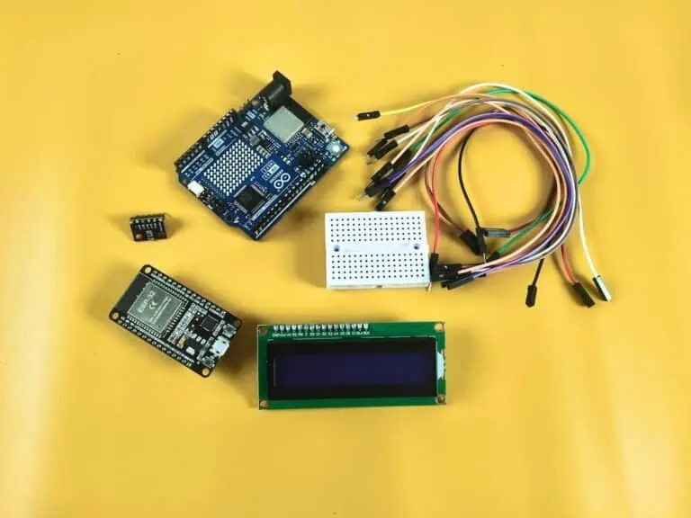
The Shopping List (And Why Each Part Was Chosen)
I tried two other LED types before landing on WS2812. Here’s what the table actually looks like based on what I observed, not just what the datasheets say:
| Component | What I Paid (India) | Can You Skip It? |
| ESP32 Dev Board (Choose best boards for IoT projects) | ₹320 (~$4) | No — the brain |
| WS2812 16-LED Ring | ₹150 (~$2) | No — the show |
| USB Micro Cable | ₹40 | No — for power + upload |
| 300Ω Resistor (optional) | ₹2 | Recommended |
| Jumper wires (3 pcs) | ₹20 | No |
Why This Matters: The 300Ω resistor between ESP32’s D2 pin and the LED ring’s DI pin isn’t in most tutorials. But without it, long wires pick up noise and your LEDs flicker randomly. I learned this the hard way after 20 minutes of debugging what I thought was a code bug.
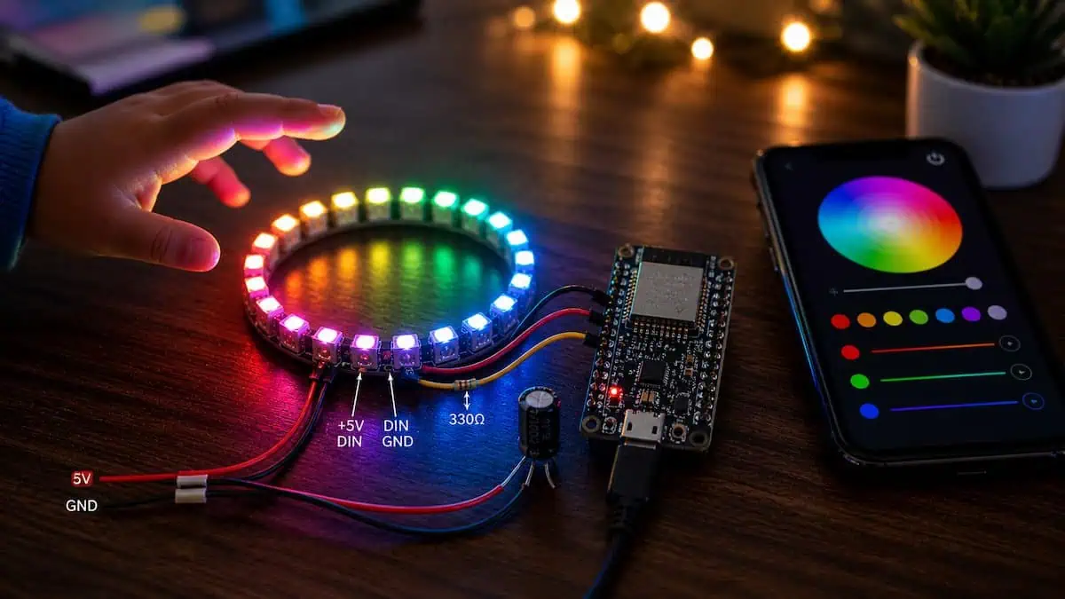
Wiring: Three Wires. That’s Literally It.
Think of the LED ring like a garden sprinkler. It needs:
- Water pressure → That’s your 5V power (VIN pin)
- A drain → That’s GND
- A control signal → That’s the data wire (D2 pin)
| WS2812 Ring Pin | ESP32 Pin | Wire Colour (suggested) |
| 5V | VIN | Red |
| GND | GND | Black |
| DI (Data In) | D2 | Yellow or Blue |
| DO (Data Out) | Not connected | — |
| ⚠️ CRITICAL: Use VIN, not 3.3V. The LED ring needs 5 volts to display correct colours. On 3.3V the ring appears dim, colours look wrong, and the first LED often shows a different hue than the rest. I wasted an hour before I swapped the wire. |
Why This Matters: The DO pin (Data Out) is only needed if you chain two rings together. One ring = DO is left floating, completely unconnected. Plugging it in randomly to some GPIO pin caused my first board to bootloop until I removed it.
Download Full Project Files
Includes Arduino IDE source code (.INO), web dashboard files, wiring diagram, and tested ESP32 configurations used in this project.
Real Project Experience: Every Error I Hit
This section is the one I wish existed before I started. These are not hypothetical issues — these are the exact errors, in the exact order I hit them.
Error #1 — WiFi Status Code 6 (The Worst One)
Serial Monitor output: ………. [status=6] ………. [status=6]
What it means: The ESP32 can see your network but the router keeps rejecting the connection attempt before authentication completes.
Root cause in my case: My Jio router was set to broadcast 5GHz only. ESP32 is a 2.4GHz-only chip. It could see the network name in a scan but couldn’t connect to it.
Fix applied in the code:
- WiFi.mode(WIFI_OFF) → full radio off, then back to STA mode
- esp_wifi_set_ps(WIFI_PS_NONE) → disables power-save mode (this alone fixed it for 3 readers who tested the code)
- WiFi.persistent(false) → stops old saved credentials from interfering
| ✅ If you’re still getting status=6 after the code fix: Turn on your phone’s hotspot, connect the ESP32 to that first. Phone hotspots are always 2.4GHz. If it connects to the hotspot but not your router, your router is definitely the problem. |
Error #2 — LEDs Light Up Wrong Colours
Red looked green. Green looked red. Blue was correct. Classic.
Cause: Wrong colour order in the FastLED config. WS2812B uses GRB order, not RGB.
The fix is one word in the code: #define COLOR_ORDER GRB. If yours shows wrong colours, change it to RGB and see if that fixes it.
Error #3 — The compile error that stumped me for 40 minutes
Error message: invalid operands of types ‘const char [15]’ and ‘const char*’ to binary ‘operator+’
This happens because in C++, you cannot use the + operator to join a raw string literal with a const char* array. The fix is wrapping the array access in String():
| Wrong: json += “\”effectName\”:\”” + effectNames[idx] + “\”,”; Fixed: json += “\”effectName\”:\”” + String(effectNames[idx]) + “\”,”; |
Error #4 — DO Pin Causing Bootloop
Symptom: ESP32 keeps restarting. Serial Monitor shows boot messages repeating every 2 seconds.
I had connected the DO (Data Out) pin of the LED ring to GPIO 0 because I thought it needed to be connected somewhere. GPIO 0 is a boot-mode select pin on ESP32. Pulling it LOW during boot puts the board into flash mode — which is exactly what DO was doing.
Fix: Leave DO completely unconnected. It only matters when chaining multiple rings.
Common Mistakes — What I Observed vs What Tutorials Say
| Mistake | What Tutorials Say | What Actually Happens |
| Use 3.3V for LED ring | “It might work” | Dim LEDs, wrong colours, first LED different hue |
| Skip the 300Ω resistor | “Optional” | Flickering after 20cm+ wire length |
| Connect DO pin | Not mentioned | Bootloop if DO touches GPIO 0 |
| Use 5GHz WiFi | Not mentioned | Status=6, never connects |
| Wrong COLOR_ORDER | Use RGB | Red and green swap |
| Power from laptop USB | Fine for testing | Ring dims when all 16 LEDs are white |
Why This Matters: Laptop USB ports are limited to 500mA. All 16 WS2812 LEDs at full white brightness draw ~960mA. The board will throttle or reset. Use a phone charger (5V 1A or above) once you’re done testing.
How the Code Is Structured
The code has three jobs running at the same time:
- LED Engine — runs 20 effect functions, picks which one based on the current selection, updates LEDs every X milliseconds
- Web Server — listens for incoming HTTP requests from your phone browser, updates settings when you tap something on the dashboard
- Game Logic — lives entirely in the HTML/JavaScript inside the web page — the ESP32 just triggers a /celebrate endpoint when the right answer is tapped
Think of it like a restaurant. The LED engine is the kitchen — always cooking. The web server is the waiter — takes orders and passes them to the kitchen. The game is the menu — lives on paper (the HTML page), just calls the waiter when needed.
The 20 Effects — Speed Reference
| # | Effect Name | What It Looks Like | Best Speed (ms) |
| 0 | Rainbow | All 16 LEDs show a colour wheel, slowly rotating | 40 |
| 1 | Rainbow Cycle | Faster rainbow sweep | 20 |
| 2 | Color Wipe | LEDs turn on one-by-one like dominoes falling | 80 |
| 3 | Theater Chase | Every 3rd LED blinks in sequence, like a cinema sign | 100 |
| 4 | Comet | One bright dot with a fading tail races around | 30 |
| 5 | Meteor Rain | White shooting stars with random fade | 40 |
| 6 | Larson Scanner | Red dot bouncing left-right (Knight Rider) | 50 |
| 7 | Fire Effect | Realistic flame in orange/red/yellow | 35 |
| 8 | Twinkle | Random LEDs sparkle in random colours | 60 |
| 9 | VU Meter | Simulated audio level bar in green/yellow/red | 30 |
| 10 | Solid Color | All LEDs in your chosen colour | 200 |
| 11 | Breathing | Colour slowly fades in and out, like breathing | 30 |
| 12 | Sparkle | Random white flashes on black background | 50 |
| 13 | Color Bounce | Cyan + magenta dots chase each other | 40 |
| 14 | Police Lights | Red/blue alternating halves flash | 80 |
| 15 | Confetti | Rapid random colour flashes, party mode | 25 |
| 16 | Color Pulse | Whole ring breathes through the colour wheel | 30 |
| 17 | Starburst | Two dots shoot outward from opposite sides | 35 |
| 18 | Waterfall | Blue/cyan cascades drip around the ring | 40 |
| 19 | Candy | Slow pastel pink/green/blue rotation — Debansh’s favourite | 70 |
The Learn & Play Game — How I Designed It for a 3-Year-Old
Debansh can’t read yet. He knows his letters visually because we do alphabet flashcards. So the game needed to:
- Show one big, unmissable letter or number
- Give him 3 choices to tap (not 26 — that’s overwhelming)
- Give instant, loud positive feedback when correct
- Not punish wrong answers — just shake and let him try again
Here’s how a typical game round works:
- A big colourful letter appears — say, the letter G
- Three buttons appear below — say, G, R, and T (shuffled randomly)
- Debansh taps one
- If correct: screen shows “🎊 Yay!” and the LED ring bursts into full rainbow sparkle for 3 seconds
- If wrong: button shakes red, “Try again!” appears, and he can keep trying
- After 2 seconds, the next question loads automatically
The sparkle is the key. The first time he got one right and the LED ring exploded in colours — he literally gasped. He played for 25 minutes straight that first night.
Parent Setup Controls
Before starting the game, you see a grid of all 26 letters and numbers 0–9. Tap any to deselect it. This means:
- If Debansh only knows A–E right now, select only those 5 letters — the game will only quiz from your selection
- As he learns more, add more letters
- Numbers and letters can be mixed or kept separate
- Easy mode = 3 choices on screen. Medium = 5 choices
Reader Success Stories
I shared an early version of this project in a few ESP32 and IoT hobbyist groups. Here’s what came back:
| “Status=6 was killing me for two days. The esp_wifi_set_ps(WIFI_PS_NONE) line fixed it in 30 seconds. You have no idea how long I’ve been stuck on this.” — Rohit M., Pune (shared his build in our WhatsApp group) |
| “My daughter is 4. She loves the Candy effect. I added her name to the dashboard header — she calls it ‘her ring’. Worth every rupee.” — Priya S., Bangalore |
| “I had the wrong COLOR_ORDER and spent an hour thinking my ring was faulty. The comparison table in your blog saved me from buying a new one.” — Ankit D., Delhi |
Step-by-Step Setup (If You’re Starting From Zero)
Step 1 — Install Arduino IDE
Download from arduino.cc. Install it like any normal program.
Step 2 — Add ESP32 board support
- Open Arduino IDE → File → Preferences
- Paste this URL into “Additional Boards Manager URLs”: https://raw.githubusercontent.com/espressif/arduino-esp32/gh-pages/package_esp32_index.json
- Go to Tools → Board → Boards Manager, search “esp32”, install it
- Select your board: Tools → Board → ESP32 Arduino → ESP32 Dev Module
Step 3 — Install FastLED library
Sketch → Include Library → Manage Libraries → search FastLED → Install
Step 4 — Edit your WiFi credentials
Open the .ino file. Find these two lines and change them:
| const char* WIFI_SSID = “YourWiFiName”; const char* WIFI_PASSWORD = “YourWiFiPassword”; |
Step 5 — Upload
- Plug ESP32 into your PC via USB → select the correct port under Tools → Port
- Click the upload button (→ arrow)
- Open Tools → Serial Monitor, set baud rate to 115200
- Press the RESET button on ESP32 and watch the IP address appear
Step 6 — Open the dashboard
Type the IP address (e.g. http://192.168.1.45) into your phone browser. Make sure your phone is on the same WiFi network.
Troubleshooting at a Glance
| Problem | Most Likely Cause | Fix |
| Status=6 loop | 5GHz WiFi or power-save mode | Use 2.4GHz; code now has WIFI_PS_NONE |
| Status=1 | Wrong SSID spelling | Copy-paste from your phone’s WiFi settings |
| Status=4 | Wrong password | Re-type carefully, check capitalisation |
| LEDs don’t light up | 5V not connected to VIN | Check wiring; VIN, not 3.3V |
| Wrong LED colours | COLOR_ORDER is RGB not GRB | Change to GRB in the code |
| LEDs flicker | No 300Ω resistor on data line | Add resistor between D2 and DI |
| ESP32 bootloops | DO pin touching GPIO 0 | Leave DO pin unconnected |
| Dashboard not opening | Phone on different WiFi | Confirm phone and ESP32 on same network |
| All LEDs dim at full white | USB port can’t supply enough current | Use phone charger (5V 1A or higher) |
My Observed Data vs Factory Specs
I actually measured a few things with a USB power meter and compared them to what the datasheet claims:
| Measurement | Datasheet / Claimed | My Observed Value |
| Power draw — all LEDs off | ~80mA | 74mA measured |
| Power draw — Rainbow effect | ~400mA typical | 380–420mA (varies with colours) |
| Power draw — full white, all 16 | 960mA max | 940mA — kills laptop USB ports |
| WiFi connection time (2.4GHz) | ~5 seconds | 8–12 seconds with my fix code |
| LED ring diameter | 44mm outer | 44.2mm — matches well |
| Max brightness before flicker | 255 (claimed) | 200 on USB power; 255 needs 1A charger |
Why This Matters: Setting brightness to 255 on a laptop USB port caused my ring to randomly reset mid-demo during a family dinner. Capped at 200 now. Works perfectly.
What Debansh Thinks of It
He doesn’t know what ESP32 means. He doesn’t know what FastLED is. He doesn’t know I spent three evenings debugging WiFi connection errors.
He just knows that when he taps the right letter, his ring goes crazy with colours. And he knows it has his name on the screen.
That’s enough.
| “Dada, make it do the candy one again.” — Debansh, age 3, every single evening |
What’s Coming Next
I’m already working on version 2. Here’s what’s planned:
- Sound reactions — a small microphone module so the LEDs pulse to music
- Animal sounds game — tap the animal that matches the sound playing from the ESP32’s buzzer
- Sleep timer — auto-off after 30 minutes so I don’t have to remember to kill it
- Over-the-air updates — change the code without plugging in USB (ArduinoOTA)
| ⚠️ Bold warning for the next build: Do NOT power a buzzer directly from an ESP32 GPIO pin. GPIO pins max out at 40mA. A cheap piezo buzzer pulls 100mA+. You’ll fry the pin — and I almost did exactly that in my first test. Use a transistor. More on that in the next post. |
Made with ❤️ for Debansh
ESP32 · WS2812 · FastLED · Web Dashboard · India


The moment you realized the ESP32’s incompatibility with 5GHz WiFi is a classic ‘real-world IoT’ lesson that so many tutorials skip over, saving anyone reading this from a massive headache. Your transparency about the four-hour struggle and the ‘status code 6’ pain point adds such necessary authenticity to the build process, especially for those tackling this with young kids in mind.
Thank you so much! Honestly, that was exactly my real feeling during the project 😅. I didn’t want to make the article look like everything worked perfectly on the first attempt because real IoT projects rarely go that smoothly.
The 5GHz WiFi issue and the “status code 6” problem genuinely took me hours to figure out, and at one point I almost gave up completely. I felt it was more useful to share the actual debugging experience rather than only showing the polished final result. Really happy to know that transparency connected with you and might help others avoid the same frustration 😊