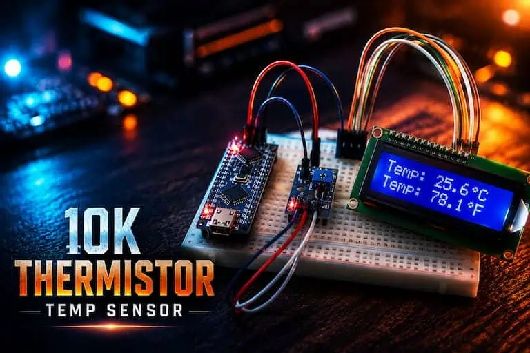
10K Thermistor Temperature Sensor Module with Arduino
Introduction
There’s a reason the 10K thermistor module is usually the second sensor a beginner buys, right after the ultrasonic distance sensor. It’s cheap, it’s simple, and it teaches you something that digital sensors quietly hide from you: how a raw voltage actually becomes a real-world measurement.
If you’ve ever stared at an ADC reading like 542 and wondered how that number turns into “23.4°C,” this guide is going to make that click for you. We’re going to wire the module, write the code, understand the math behind it, and — just as importantly — talk about when this sensor is genuinely the right choice and when it isn’t.
Why Use a 10K Thermistor Temperature Sensor Module?
Most beginners reach for the DHT11 or a DS18B20 because tutorials tell them to. Fair enough — those are solid sensors. But the 10K thermistor module has a few things going for it that digital sensors don’t.
It’s fast. There’s no communication protocol, no timing delays, no waiting for a sensor to respond. You read an analog pin and you get a value, instantly, every single loop.
It’s cheap enough to use five of them in one project without thinking twice about your budget. Try doing that with a handful of BMP280 and watch your BOM cost climb.
And it’s a genuinely good way to learn the fundamentals — voltage dividers, ADC behavior, resistance-temperature relationships — concepts that show up again and again in electronics, way beyond just this one module.
🔧 Engineering Note: A thermistor isn’t a “temperature sensor” in the way a DS18B20 is. It’s a resistor. Everything else — the module, the math, the code — exists to turn that resistance into a temperature you can actually use.
What You’ll Learn in This Guide
By the end of this, you’ll know how the module works internally, how to wire it correctly the first time, how to write Arduino code that converts raw analog readings into accurate temperature values, and how to avoid the mistakes that trip up almost every beginner working with analog sensors. We’ll also get into real applications and a few engineering trade-offs worth thinking about before you commit to this sensor for a project.
What Is a 10K Thermistor Temperature Sensor Module?
A thermistor is a resistor whose resistance changes predictably with temperature. “10K” refers to its resistance at 25°C — the reference temperature manufacturers use for rating these components. At room temperature, this thermistor sits at roughly 10,000 ohms. Heat it up, and the resistance drops. Cool it down, and the resistance climbs. That’s an NTC thermistor — Negative Temperature Coefficient — and it’s what almost every low-cost thermistor module on the market uses.
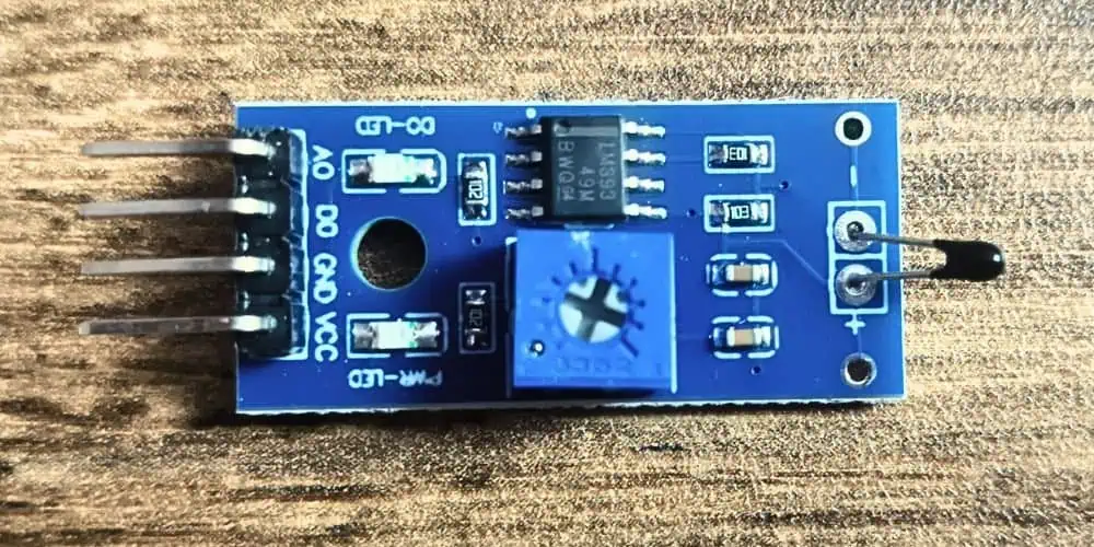
The “module” part is just a small breakout board: the thermistor itself, a fixed resistor already wired into a voltage divider, and three pins — VCC, GND, and an analog output (often labeled AO or A0). Some modules also include a digital output pin (DO) with an onboard comparator and a potentiometer, useful for simple threshold-triggering projects like “turn on a fan above 30°C,” though most Arduino temperature-monitoring projects use the analog pin.
How Does the 10K Thermistor Temperature Sensor Module Work?
Here’s where the voltage divider analogy earns its keep.
Think of a voltage divider as two garden hoses connected in series, water flowing from a full tank (5V) down to an empty one (GND). The pressure you measure at the junction between the two hoses depends on how restrictive each hose is. Make one hose narrower, and more pressure builds up on that side of the junction.
That’s exactly what’s happening electrically. The thermistor and the fixed resistor form a series pair between 5V and GND. As temperature changes, the thermistor’s resistance changes, which shifts how the 5V is “divided” between the two components. Arduino’s ADC reads the voltage at that junction and converts it into a number between 0 and 1023.
The catch: that number alone doesn’t tell you the temperature. It tells you a voltage ratio. Getting from voltage ratio to resistance, and then from resistance to temperature, is where the actual engineering happens — and we’ll walk through that math shortly.
💡 Pro Tip: If you already understand how a potentiometer works as a voltage divider, you already understand 80% of how this module works. The thermistor is just a resistor that changes its own value based on temperature instead of you turning a knob.
10K Thermistor Temperature Sensor Module Pinout
Most modules ship with a simple 3-pin or 4-pin layout:
| Pin | Function |
| VCC | Connect to 5V (or 3.3V depending on your board) |
| GND | Connect to ground |
| A0 (AO) | Analog output — connect to an Arduino analog pin |
| D0 (DO) | Digital threshold output (optional, present on some modules) |
Double-check your specific module’s silkscreen labeling before wiring — cheaper modules from different manufacturers occasionally shuffle pin order, and this is one of those small details that causes a surprising number of “my sensor isn’t working” forum posts.
Technical Specifications
| Parameter | Typical Value |
| Resistance at 25°C | 10,000 Ω (10K) |
| Operating Voltage | 3.3V – 5V |
| Beta (B) Coefficient | ~3950K (check your module’s datasheet — this varies) |
| Temperature Range | -55°C to +125°C (thermistor itself; module range often narrower) |
| Output Type | Analog voltage (plus digital threshold on some boards) |
| Response Time | A few seconds (slower than you’d expect — more on this later) |
| Interface | Simple analog read, no library required |
⚠ Common Mistake: Assuming every 10K thermistor module uses the same Beta coefficient. It doesn’t. Using the wrong Beta value is one of the most common reasons people get temperature readings that are “close but off by a few degrees.” Check your module’s documentation, or calibrate it yourself — we’ll cover that later.
Bill of Materials (This Build)
| Component | Role |
|---|---|
| Arduino Nano | Microcontroller (ATmega328P, 5V logic) |
| 10K thermistor temperature sensor module | Temperature sensing |
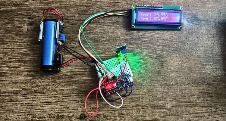
| 1x 18650 Li-ion cell | Portable power source (3.0–4.2V) |
| TP4056 module | Charges the 18650 over USB, basic charge protection |
| MT3608 boost converter | Steps battery voltage up to a stable 5V rail |
| LCD1602 with PCF8574 I2C backpack | Standalone readout, only 2 signal wires (SDA/SCL) |
| Breadboard + jumper wires | Prototyping |
| Multimeter | Wiring checks and Beta-coefficient calibration |
Arduino Nano Pinout Reference (Relevant Pins Only)
| Nano Pin | Used For |
|---|---|
| 5V | Power in from MT3608 output; also powers thermistor module and LCD |
| GND | Common ground for battery circuit, thermistor, and LCD |
| A0 | Thermistor module analog output (AO) |
| A4 | LCD1602 I2C data line (SDA) |
| A5 | LCD1602 I2C clock line (SCL) |
⚠ Common Mistake: On a Nano, A4/A5 are hardwired to the I2C bus — you can’t relocate SDA/SCL to other analog pins the way you might on some other boards. Keep A0 free for the thermistor and leave A4/A5 dedicated to the LCD.
Powering the Project from a Single 18650 Battery
This is the part that trips people up most, so let’s be precise about it.
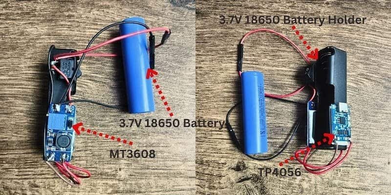
The chain: 18650 cell → TP4056 (charge management) → MT3608 (boost to 5V) → Nano’s 5V pin.
- 18650 cell → TP4056. Solder or clip the battery’s positive and negative leads to the TP4056’s
B+andB-pads. The TP4056 handles charging when a USB cable is plugged into it; it is not a boost converter and does not regulate output voltage during normal use — it just charges the cell and passes battery voltage through toOUT+/OUT-. - TP4056
OUT+/OUT-→ MT3608IN+/IN-. The 18650’s voltage swings from about 4.2V (full) down to 3.0V (discharged) — too low and too unstable to power a Nano’s 5V rail directly. The MT3608 boost-converts that swinging voltage up to a fixed 5V. - Set the MT3608 output before connecting it to the Nano. Power the MT3608 from the battery alone, measure its output pad with a multimeter, and turn the onboard potentiometer until it reads a steady 5.0V. Skipping this step is the single most common way to damage a Nano on a first battery build — an unset MT3608 can output well above 5V.
- MT3608
OUT+/OUT-→ Nano5VandGNDpins. Feed the regulated 5V directly into the Nano’s 5V pin (notVIN), sinceVINroutes through the Nano’s onboard linear regulator and expects a higher unregulated input. Feeding 5V intoVINwastes headroom the regulator needs and can under-power the board. - Tap the same 5V/GND rail for the thermistor module’s VCC/GND and the LCD’s VCC/GND, so everything shares one common ground — this matters for the I2C bus to behave correctly.
✅ Best Practice: Add a small on/off switch between the TP4056’s OUT+ and the MT3608’s IN+ so you can power the whole project down without unplugging wires, while charging can still happen independently through the TP4056’s USB port.
⚠ Common Mistake: Charging and running the circuit at the same time on a bare TP4056 works, but many low-cost TP4056 boards have thin trace protection and no true load-sharing IC — for anything left unattended, prefer a TP4056 variant with built-in protection circuitry (marked with an extra IC labeled “protection” near the battery pads).
Adding a Parallel LCD1602 Display via I2C
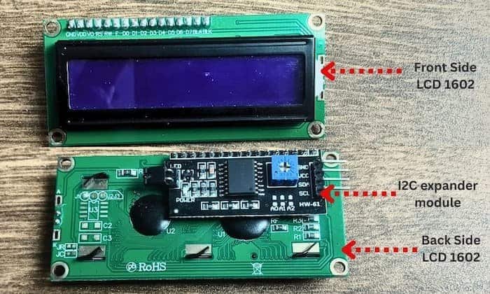
A bare LCD1602 needs 6+ signal pins, which eats most of a Nano’s I/O. The I2C backpack (a small board soldered to the back of the LCD, usually built around a PCF8574 chip) collapses that down to two wires.
- LCD1602 (I2C backpack) VCC → Nano 5V
- LCD1602 GND → Nano GND
- LCD1602 SDA → Nano A4
- LCD1602 SCL → Nano A5
Most I2C backpacks default to address 0x27, with some at 0x3F. If your display shows nothing but the backlight turns on, the address is the first thing to check — run an I2C scanner sketch (search “Arduino I2C scanner,” a widely used 15-line utility sketch) to confirm the address before troubleshooting anything else.
💡 Pro Tip: The contrast potentiometer is on the back of the LCD module itself, not the I2C backpack. A blank, backlit screen with correct wiring is almost always just the contrast pot needing adjustment.
Wiring Summary
18650 (+) ──► TP4056 B+          TP4056 OUT+ ──► MT3608 IN+          MT3608 OUT+ ──► Nano 5V ──┬──► Thermistor VCC
18650 (-) ──► TP4056 B-          TP4056 OUT- ──► MT3608 IN-          MT3608 OUT- ──► Nano GND ─┤    Thermistor GND
                                                                                                  ├──► LCD1602 I2C VCC
                                                                                                  └──► LCD1602 I2C GND

Thermistor A0 ──► Nano A0
LCD1602 SDA   ──► Nano A4
LCD1602 SCL   ──► Nano A5
See the pinout diagram at the top of this guide for the visual layout.
Determining Your Thermistor’s Beta Coefficient (Step-by-Step)
Most guides tell you to plug in 3950 and move on. That’s a generic value, and it’s frequently wrong for the specific thermistor in your module. Here’s how to measure your own.
What you need: a multimeter with resistance mode, two temperature reference points you can hold steady (ice water and warm/hot water work well), a separate accurate thermometer to confirm the water temperature, and the thermistor itself disconnected from the circuit.
Step 1 — Prepare two reference baths.
- Bath 1: Ice water. Crushed ice + a little water, stirred, left a minute to stabilize. Confirm with your reference thermometer — it should read close to 0°C.
- Bath 2: Warm water, somewhere around 50–60°C is a good spread from bath 1. Confirm the exact reading with your reference thermometer — don’t assume, measure it.
Step 2 — Measure resistance at T1 (ice bath).
Disconnect the thermistor from the module circuit. Set your multimeter to resistance mode, touch the probes to the thermistor’s two leads, and submerge the bead (not the leads/solder joints) in the ice bath. Wait about 30–60 seconds for the reading to stabilize, then record R1 (in ohms) and T1 (the thermometer’s reading, in °C).
Step 3 — Measure resistance at T2 (warm bath).
Dry the thermistor, then repeat in the warm bath. Record R2 (in ohms) and T2 (in °C).
Step 4 — Convert both temperatures to Kelvin.
T1(K) = T1(°C) + 273.15
T2(K) = T2(°C) + 273.15
Step 5 — Calculate Beta.
B = ln(R1 / R2) / ( (1/T1) − (1/T2) )Where ln is the natural logarithm, R1/R2 are in ohms, and T1/T2 are in Kelvin.
Step 6 — Plug your measured B into the code,
replacing the generic 3950.0 constant. If you also measured your thermistor’s resistance precisely at 25°C (a third bath, or careful room-temperature measurement with the reference thermometer confirming exactly 25.0°C), update NOMINAL_RESISTANCE too instead of assuming a perfect 10,000Ω.
✅ Best Practice: Repeat the two-bath measurement two or three times and average the resulting B values — a single noisy reading (thermistor not fully settled, water not fully stirred) can throw off the calculation more than you’d expect.
⚠ Common Mistake: Measuring resistance while the thermistor is still wired into the module’s voltage divider. You’ll be measuring a combined resistance, not the thermistor alone — always disconnect it first.
Arduino Code (Nano + I2C LCD1602)
#include <math.h>
#include <Wire.h>
#include <LiquidCrystal_I2C.h>

// ---- LCD Setup ----
// Change 0x27 to 0x3F if your I2C scanner found that address instead
LiquidCrystal_I2C lcd(0x27, 16, 2);

// ---- Pin & Circuit Constants ----
#define THERMISTOR_PIN A0
#define SERIES_RESISTOR 10000.0     // Fixed resistor on the module (ohms)
#define NOMINAL_RESISTANCE 10000.0  // Thermistor resistance at 25°C — update if you measured your own
#define NOMINAL_TEMPERATURE 25.0    // Reference temperature (°C)
#define BCOEFFICIENT 3950.0         // Replace with YOUR measured Beta coefficient
#define ADC_MAX 1023.0
#define NUM_SAMPLES 10              // Averaging window to reduce jitter

void setup() {
  Serial.begin(9600);
  lcd.init();
  lcd.backlight();
  lcd.setCursor(0, 0);
  lcd.print("Thermistor Init");
  delay(1000);
  lcd.clear();
}

void loop() {
  // Average several ADC samples to smooth out noise
  long total = 0;
  for (int i = 0; i < NUM_SAMPLES; i++) {
    total += analogRead(THERMISTOR_PIN);
    delay(10);
  }
  float adcValue = total / (float)NUM_SAMPLES;

  // Convert ADC reading to resistance
  float resistance = SERIES_RESISTOR / (ADC_MAX / adcValue - 1.0);

  // Beta parameter equation (simplified Steinhart-Hart)
  float steinhart = resistance / NOMINAL_RESISTANCE;
  steinhart = log(steinhart);
  steinhart /= BCOEFFICIENT;
  steinhart += 1.0 / (NOMINAL_TEMPERATURE + 273.15);
  steinhart = 1.0 / steinhart;
  steinhart -= 273.15; // Kelvin to Celsius

  float fahrenheit = (steinhart * 9.0 / 5.0) + 32.0;

  // Serial output for debugging
  Serial.print("ADC: ");
  Serial.print(adcValue);
  Serial.print(" | R: ");
  Serial.print(resistance);
  Serial.print(" ohm | Temp: ");
  Serial.print(steinhart);
  Serial.print(" C | ");
  Serial.print(fahrenheit);
  Serial.println(" F");

  // LCD output
  lcd.setCursor(0, 0);
  lcd.print("Temp: ");
  lcd.print(steinhart, 1);
  lcd.print((char)223); // degree symbol
  lcd.print("C   ");

  lcd.setCursor(0, 1);
  lcd.print("Temp: ");
  lcd.print(fahrenheit, 1);
  lcd.print((char)223);
  lcd.print("F   ");

  delay(1000);
}
Library note: install LiquidCrystal_I2C via the Arduino Library Manager (search “LiquidCrystal I2C” — the Frank de Brabander or Marco Schwartz fork are both common and work fine here).
Code Explanation
The constants block is unchanged from a standard build — resistor value, nominal resistance, reference temperature, and your measured Beta coefficient. The averaging loop takes 10 quick ADC samples before running the conversion math, which noticeably smooths out the jitter you’d otherwise see on a breadboard build.
lcd.init() and lcd.backlight() bring the I2C LCD online. Everything downstream of the temperature math is duplicated to both Serial.print (for debugging over USB) and the LCD (for a standalone, no-computer readout) — handy once the whole thing is running off the 18650 and disconnected from a laptop.
🔧 Engineering Note: The degree symbol ((char)223) is a quirk of the HD44780 character set most LCD1602 modules use — it renders correctly on the display even though it looks like a stray character in the code.
Testing Procedure
- Set the MT3608 to a confirmed 5.0V before wiring it to the Nano.
- Upload the code with the Nano still connected via USB (for easier debugging), then disconnect and switch to battery power to confirm it runs standalone.
- Confirm the LCD shows a sensible room-temperature reading on power-up.
- Gently pinch the thermistor bead between two fingers and watch both the Serial Monitor and LCD track the rise.
- If the readings look wildly wrong, recheck your Beta coefficient calculation before assuming the sensor or wiring is at fault.
Engineering Tips
- Averaging is already built into the code above — if it’s still noisy, increase
NUM_SAMPLES. - A dropping 18650 charge level shifts the whole circuit’s assumed 5V reference unless the MT3608 is holding a genuinely stable 5V output under load — check output voltage under load (LCD backlight on, Nano running), not just at idle.
- If you’re running this fully portable, budget for the LCD backlight — it’s usually the single biggest current draw in this build and will noticeably shorten runtime on one 18650 cell versus running the LCD backlight off.
Common Beginner Mistakes
⚠ Common Mistake #1: Wiring the thermistor and fixed resistor in the wrong order relative to what the code assumes. Readings moving backward — colder as things heat up — is almost always this.
⚠ Common Mistake #2: Using a generic Beta value of 3950 without measuring your own. See the calibration steps above.
⚠ Common Mistake #3: Connecting the MT3608 to the Nano before setting its output to 5V. This is the build’s highest-risk step — always set voltage under battery power first, with nothing else connected downstream.
⚠ Common Mistake #4: Expecting instant response. Thermistors have thermal mass and respond over a few seconds — this isn’t a code problem, it’s physics.
Troubleshooting
LCD backlight on, nothing displayed.
Almost always the contrast potentiometer on the back of the LCD module — turn it until text appears.
LCD completely dark, no backlight.
Check the I2C address with a scanner sketch, and confirm SDA/SCL are on A4/A5, not swapped.
Readings stuck at 0 or 1023.
Wiring fault — check VCC/GND aren’t swapped and A0 is actually connected to the thermistor’s analog pin.
Nano won’t power on from battery.
Confirm the MT3608 output is actually 5V under load (not just idle), and that it’s feeding the Nano’s 5V pin, not VIN.
Runtime shorter than expected on one 18650.
Expected — a single cell with an LCD backlight and boost converter running continuously is a modest runtime budget. Consider a higher-capacity 18650 or a low-power LCD-off sleep mode between readings if runtime matters.
Frequently Asked Questions
Can I skip the MT3608 and power the Nano directly from the 18650?
Not reliably. A single 18650 (3.0–4.2V) is below the ~4.5–5.5V a Nano’s 5V rail needs when fed directly, and above what most peripherals expect if fed into VIN without headroom. The boost converter is doing real work here.
Do I need the TP4056 if I’m just using disposable batteries?
No — TP4056 is specifically for rechargeable Li-ion cells like the 18650. Skip it entirely if you’re using non-rechargeable batteries, but then you also lose the ability to recharge in place.
Why measure Beta myself instead of using the datasheet value?
Component tolerances on cheap thermistor modules are real. A measured Beta from your actual unit is almost always more accurate than a generic datasheet number, and the two-bath method takes about 15 minutes.
Can I use a 20×4 LCD instead of a 16×2?
Yes — the I2C wiring is identical; just change the LiquidCrystal_I2C lcd(0x27, 16, 2); line to lcd(0x27, 20, 4); and adjust your cursor positions.
Conclusion
Swapping in a Nano, running the whole thing off a single rechargeable 18650, and adding a standalone I2C LCD turns this from a breadboard demo into something you could actually leave running in a fridge, incubator, or terrarium. And measuring your own Beta coefficient — rather than trusting a generic 3950 — is the difference between “close enough” and readings you can actually trust.