
Arduino Nano ADXL345 Digital Level: A 2-Axis Inclinometer with ZERO Reference and Parallel Surface Check
The Problem This Project Solves
Anyone who has mounted a distribution board, aligned a cable tray, or leveled a machine base knows the annoyance of carrying a bubble level around and squinting at a tiny glass vial. A bubble level tells you if something is horizontal. It does not tell you whether two separate surfaces — say, two mounting brackets ten meters apart — sit at the same angle as each other, even if neither one is perfectly horizontal.
That second question comes up constantly in real installation work. If you’re bolting a support frame to two brackets that are both tilted 3° for drainage or structural reasons, you don’t care whether they’re level with the earth — you care whether they’re level with each other.
This project is a small battery-powered digital level built around an Arduino Nano and an ADXL345 accelerometer that answers both questions: is this surface level with gravity, and is this surface parallel to another surface I measured earlier.
What We Are Building
The device is a handheld electronic inclinometer with:
- An OLED screen showing a moving dot that represents surface tilt in two directions (X and Y)
- Numeric X/Y angle readout in degrees
- A ZERO button that lets you store the current tilt as a new reference point
- A RESET button that discards that reference and goes back to gravity-horizontal
- A rechargeable LiPo battery with onboard charging
It is a 2-axis surface level. The ADXL345 itself measures acceleration on three axes, but a flat surface only has two independent tilt directions — pitch and roll, referred to here simply as X and Y. The Z-axis reading is used internally as part of the gravity-vector math but is not a separate tilt direction you can point the device in. Calling this a “3-axis inclinometer” would be inaccurate, so that phrasing is avoided throughout.
How the Digital Level Actually Works
The ADXL345 does not measure angle. It measures acceleration along X, Y, and Z. When the device is sitting still on a surface, the only meaningful acceleration acting on it is gravity — roughly 1g, pointing straight down.
Because gravity always points the same direction, the proportion of that 1g vector appearing on each axis tells you how the sensor is tilted relative to “down.” If the device is perfectly flat, nearly all of that gravity vector shows up on Z, and X and Y read close to zero. Tilt the device, and gravity starts projecting onto X and/or Y instead.
The Arduino reads the three raw acceleration values and runs them through atan2() to convert that vector geometry into an angle in degrees. This is a standard technique for static tilt sensing — the sensor supplies force data, the microcontroller supplies the trigonometry.
This distinction matters because it explains the sensor’s limits later: anything that adds acceleration other than gravity (vibration, sudden movement, shock) will corrupt the angle calculation, because the math assumes gravity is the only force present.
Why ADXL345 Instead of MPU6050
The MPU6050 was the initial candidate for this build, since it’s the more commonly recommended “IMU” module in beginner projects. It’s worth explaining why it was dropped in favor of the ADXL345.
| MPU6050 | ADXL345 | |
|---|---|---|
| Accelerometer | 3-axis | 3-axis |
| Gyroscope | 3-axis | None |
| Type | 6-axis IMU | Accelerometer only |
| Best suited for | Motion/orientation tracking, dynamic movement | Static tilt on a stationary surface |
A gyroscope measures rate of rotation, and it’s essential when a device is moving — drones, robots doing turns, anything where you need to track orientation while it changes quickly. It also helps smooth out short-term acceleration noise via sensor fusion.
This project’s actual use case is different: the device gets placed on a stationary surface and read once it settles. There’s no rotation to track, no dynamic motion to fuse. A gyroscope adds cost, complexity, and firmware overhead the project doesn’t need for that job.
To be clear, this isn’t a claim that the ADXL345 is “better” than the MPU6050 — it’s a narrower tool that matches this specific static-measurement task. If a future version of this device needs to track tilt while being carried or moved (rather than being set down and read), the MPU6050’s gyroscope would become genuinely useful, and that tradeoff is worth revisiting at that point.
Two Operating Modes: Default Gravity Level vs. ZERO Reference
This is the core feature of the project, and it’s worth explaining carefully because the two modes answer two different questions.
Mode 1 — Default Gravity Level
On power-up, the device references horizontal-to-gravity. If a surface is truly level:
X ≈ 0°
Y ≈ 0°
The dot sits at the center of the OLED screen. This mode answers: “Is this surface level with respect to gravity?”
Mode 2 — ZERO / Reference Mode
Say Surface A is intentionally tilted — a sloped mounting bracket, for example. Placing the device on it might read:
X = +5.2°
Y = -2.1°
Pressing ZERO stores this exact orientation as the new software reference. The display immediately updates to show:
X = 0.0°
Y = 0.0°
Now move the device to Surface B. If Surface B has the same angular orientation as Surface A, the dot returns close to center again — even though neither surface is anywhere near horizontal. This answers: “Is Surface B parallel to Surface A?”
This is the feature that separates this build from a basic bubble-level project, and it’s genuinely useful on site.
A Critical Clarification: Parallel ≠ Same Height
Two surfaces can be perfectly parallel while sitting at completely different elevations — think of two shelves at different heights on the same tilted wall. This device measures angular orientation only. It has no way to measure or compare absolute height or elevation between two locations. If you need to confirm both parallelism and equal height, you’ll need a separate leveling instrument (a laser level or optical level) alongside this one.
Components
| Component | Role |
|---|---|
| Arduino Nano (ATmega328P) | Main controller |
| HW-014 ADXL345 module | Accelerometer, tilt data source |
| 0.96″ 128×64 I²C OLED (SSD1306) | Display |
| ZERO push button | Set reference |
| RESET push button | Clear reference |
| 3.7V 1S LiPo battery | Power source |
| TP4056 module | Charging + protection |
| MT3608 module | Boost converter to 5V |
| Wires, connectors, enclosure/perfboard | Assembly |
BOM and Approximate Cost (India)
| Item | Approx. Price (₹) |
|---|---|
| Arduino Nano | 150 – 210 |
| HW-014 ADXL345 module | 235 – 330 |
| 0.96″ I²C OLED | 140 – 210 |
| TP4056 charger board | 10 – 20 |
| MT3608 boost converter | 30 – 50 |
| 3.7V 400mAh LiPo | 100 – 190 |
| Buttons + wiring | 20 – 40 |
| Approximate total | ₹685 – ₹1,050 |
Prices vary by seller, brand, and shipping timelines — treat this as a planning range, not a quote. Verify current prices before publishing final costs, since component pricing in the Indian hobbyist market shifts fairly often.
Power Supply
The device runs off a rechargeable 1S 3.7V LiPo rather than a raw 5V USB brick, which is what makes it genuinely portable for field use.
3.7V LiPo
   ↓
TP4056 (charging + protection)
   ↓
MT3608 (boost converter)
   ↓
regulated 5.0V
   ↓
Arduino Nano 5V pin
A few things matter here:
- Never wire a raw 3.7V LiPo straight into the Nano’s 5V pin. It’s outside the Nano’s regulated-5V input range and won’t run the board reliably.
- TP4056 only handles charging and battery protection — it is not a voltage regulator for your load.
- MT3608 is a boost converter, not a charger. Its only job is stepping the LiPo’s ~3.7–4.2V up to a stable 5V for the Nano.
- Before wiring the MT3608 output to the Nano, adjust its trimmer pot with a multimeter until the output reads exactly 5.0V. Skipping this step is the most common way to damage a Nano in a battery-powered build.
- Feed the regulated 5V into the Nano’s 5V pin, not VIN. VIN is meant for unregulated supplies above 5V (like a 9V input through the Nano’s onboard regulator); since MT3608 is already delivering a clean 5.0V, the 5V pin is the correct entry point here.
Pin Connections
HW-014 ADXL345 → Arduino Nano
| HW-014 pin | Arduino Nano | Purpose |
|---|---|---|
| 5V | 5V | Module power |
| 3V3 | Not connected | Leave unconnected |
| GND | GND | Ground |
| VS | Not connected | Leave unconnected |
| CS | 3.3V | Select I²C mode |
| SCL | A5 | I²C clock |
| SDA | A4 | I²C data |
| SDO | GND | Select I²C address 0x53 |
| IN2 | Not connected | Not required |
| IN1 | Not connected | Not required |
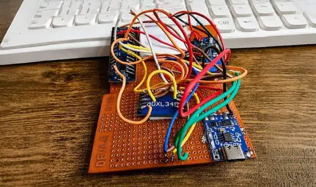
The HW-014 breakout exposes ten pins, not the generic six-pin layout you’ll see on some ADXL345 boards elsewhere — double-check your board matches this labeling before wiring, since a mismatched pinout is a common source of “sensor not found” errors.
OLED → Arduino Nano
| OLED pin | Arduino Nano |
|---|---|
| VCC | 5V |
| GND | GND |
| SDA | A4 |
| SCL | A5 |
ZERO Button
Nano D2 → ZERO button → GNDConfigured as INPUT_PULLUP — no external resistor needed.
RESET Button
Nano D3 → RESET button → GNDAlso INPUT_PULLUP — no external resistor needed.
Wiring Diagram
Both the OLED and the ADXL345 sit on the same I²C bus, sharing A4 (SDA) and A5 (SCL):
Nano A4 (SDA)
 ├── ADXL345 SDA
 └── OLED SDA

Nano A5 (SCL)
 ├── ADXL345 SCL
 └── OLED SCL
This works because I²C is a shared bus protocol — each device has its own address (OLED at 0x3C, ADXL345 at 0x53 when SDO is grounded), so the Nano can talk to both over the same two wires without conflict.
(Recommended photo placement: Photo 4 — actual wiring — goes here.)
Arduino IDE Libraries
Install these through Library Manager (Sketch → Include Library → Manage Libraries):
- Adafruit ADXL345
- Adafruit Unified Sensor
- Adafruit GFX Library
- Adafruit SSD1306
Complete Code
Complete Arduino Nano code for the ADXL345 digital level, including X/Y tilt calculation, OLED display, smoothing filter, ZERO reference, RESET function, and level indication.
arduino_adxl345_digital_level.ino
How the Code Works
readAngles()pulls raw acceleration off the ADXL345 and runs theatan2()trigonometry described in Section 3 to get instantaneous X/Y angles. Those raw values are noisy, so they’re passed through a simple exponential low-pass filter (FILTER = 0.15) that blends each new reading with the previous smoothed value — this is what keeps the OLED dot from jittering.checkButtons()debounces both buttons with a 300ms guard and updates thereferenceX/referenceYvariables — ZERO captures the current filtered angle as the new reference, RESET zeroes the reference variables back to the raw gravity baseline.drawLevel()maps the filtered, reference-adjusted X/Y values onto pixel coordinates inside a bounded box on the OLED, and prints the numeric values plus an “OK” indicator when both axes fall insideLEVEL_TOLERANCE(0.20° in this build).- The startup sequence in
setup()initializes the OLED and accelerometer, shows a boot message, then takes an initial reading and stores it as the default reference — so the device is usable a second and a half after power-on.
How to Use the Device
- Power on. Wait for the “Starting…” screen to clear.
- Place the device on the surface you want to check.
- Watch the dot — centered means level with gravity; off-center means tilted in that direction.
- Read the numeric X/Y values in degrees for a precise figure.
ZERO / Reference Operation
- Place the device on your reference surface (Surface A).
- Let the reading settle for a second or two.
- Press ZERO. The screen briefly shows “REFERENCE SET,” and the dot recenters.
- Move the device to the surface you want to compare (Surface B).
- If the dot returns near center, Surface B shares the same angular orientation as Surface A.
RESET Operation
Press RESET at any time to discard the stored reference and return to default gravity-horizontal measurement. The screen shows “DEFAULT LEVEL” briefly. This doesn’t “reset gravity” or recalibrate the sensor — it simply clears the software offset back to zero, so the device measures level relative to the earth again instead of relative to your last ZERO point.
Calibration
This build, as-is, has no dedicated calibration routine — it relies on the ADXL345’s factory-trimmed offsets and the filtering in firmware. That’s fine for comparative/practical work, but a few sources of error are worth knowing:
- Sensor offset — small manufacturing variance in the accelerometer’s zero point
- Mechanical mounting — if the ADXL345 board isn’t perfectly flat inside the enclosure, every reading inherits that tilt
- Enclosure flatness — a warped 3D-printed base introduces a fixed error
- Repeatability — how consistent readings are when placed on the same surface multiple times
- Reference surface — a machinist’s level or known-flat granite surface plate gives you a trustworthy zero point to compare against
- Temperature — MEMS accelerometers can drift slightly with temperature
- Sensor noise — random small variation in raw readings, addressed partly by the low-pass filter
A future calibration procedure could involve placing the device on a certified flat reference and a set of known angles (using a precision tilt table or shims of known height over a known base length), then recording and compensating for the offset in firmware. That’s not implemented in this version — don’t assume the out-of-box unit is calibrated to any certified standard.
Engineering Perspective: Why This Is an Inclinometer
At its core, this device works because gravity is a reliable, constant reference vector. When stationary, an accelerometer’s dominant signal is gravity, and the ratio of that signal across two axes directly encodes tilt angle — that’s the entire physical basis for MEMS-based inclinometers, from cheap hobby boards up to industrial tilt sensors.
A flat plane has exactly two independent tilt directions (commonly called pitch and roll). The third axis (Z) isn’t a separate “surface direction” — it’s the axis most aligned with gravity when the device is close to flat, and it’s mathematically necessary for computing X and Y correctly, but it doesn’t add a third tilt dimension you can point the device toward.
Static vs. dynamic acceleration matters a lot here. The angle math in Section 3 assumes gravity is the only force acting on the sensor. Pick the device up, shake it, or set it down hard, and you’re injecting extra acceleration that the math will misread as tilt for a moment. That’s precisely why a gyroscope (as in the MPU6050) becomes valuable for moving systems — it measures rotation rate independently of linear acceleration, letting sensor fusion separate “the device rotated” from “the device is briefly under g-force.” For a device that’s simply set down on a surface and read, that complexity isn’t needed.
Vibration is a related practical concern — if you’re checking a machine base while the machine is running, don’t trust the reading; vibration adds noise and transient acceleration that the filter can only partially smooth out.
Filtering, tolerance, and repeatability work together in this firmware: the low-pass filter smooths noise, LEVEL_TOLERANCE defines how close to zero counts as “OK” for the on-screen indicator, and repeatability is really a test of how consistent readings are across repeated placements — not something the firmware measures directly, but something worth checking by hand during testing.
Accuracy vs. resolution is the single most important distinction to understand before trusting a number on this screen. The display shows one decimal place (e.g., 0.1°), but that resolution says nothing about how accurate the underlying measurement actually is. Accuracy depends on sensor offset, mounting precision, filtering lag, and calibration — none of which have been formally verified against a certified reference in this build. Treat the displayed number as a useful comparative figure, not a certified measurement.
Practical Applications
- Electrical panel installation
- Distribution board mounting
- Cable tray alignment
- Equipment mounting plates
- Machine bases
- Fabrication and welding fixtures
- Workshop table leveling
- Solar panel orientation checks
- Equipment support alignment
- Verifying two surfaces are parallel before fixing a bracket between them
- Robotics ground/platform inclination checks
- Educational sensor and instrumentation experiments
This is an educational/prototype measurement tool, useful for practical field checks and learning — not a certified metrology instrument. For work requiring documented tolerances (structural, safety-critical, or regulatory contexts), use a calibrated, certified instrument instead.
Accuracy and Limitations
- The displayed decimal precision (
0.1°) is a display resolution, not a verified accuracy figure. - No formal accuracy testing against a certified reference has been performed on this build.
- Mechanical mounting, enclosure flatness, and sensor offset all introduce unverified error.
- Vibration and sudden movement will produce incorrect momentary readings.
- The device measures angular orientation only — it cannot measure elevation or height difference between two locations, even when confirming that two surfaces are parallel.
Troubleshooting
fatal error: Adafruit_ADXL345_U.h: No such file or directory This is a missing-library error, not a wiring fault. Install these four libraries via Arduino IDE Library Manager: Adafruit ADXL345, Adafruit Unified Sensor, Adafruit GFX Library, Adafruit SSD1306.
OLED stays blank Check the OLED address (0x3C) and confirm both A4/SDA and A5/SCL are shared correctly between the OLED and ADXL345. A loose ground connection on either device can also blank the display.
“ADXL345 ERROR” shown on screen Usually means the sensor isn’t responding on the I²C bus — recheck the CS pin (must go to 3.3V for I²C mode) and the SDO pin (must go to GND for address 0x53).
Dot doesn’t recenter after ZERO Confirm the ZERO button is wired to D2 and GND, and that INPUT_PULLUP is active in firmware — a floating input can cause erratic triggering.
Advanced Improvements (Future / Not in Version 1)
These are realistic upgrade paths — none of them exist in the current build:
- Adjustable level tolerance (currently a fixed constant)
- Buzzer feedback when level
- RGB status LED for at-a-glance level indication
- EEPROM storage so the reference survives a power cycle
- Multiple saved reference profiles
- Battery voltage monitoring/low-battery warning
- Z-axis diagnostic readout for debugging
- Data logging over serial
- SD card logging for field use
- Temperature compensation
- Multi-point calibration routine
- Automatic calibration on startup
- ESP32-based wireless version
- Web dashboard for remote viewing
- Smartphone monitoring app
Testing Ideas
- Place the device on a surface, note the reading, remove and replace it several times to check repeatability.
- Compare readings against a trusted machinist’s or spirit level on the same surface.
- Test the ZERO/parallel-check workflow on two physically different but intentionally matched-angle fixtures.
- Watch how readings behave under light vibration (e.g., near a running motor) to see the noise floor in practice.
Final Thoughts
This project isn’t trying to replace a certified inclinometer — it’s a genuinely useful field tool built from about ₹700–1,000 of common modules, and its ZERO/parallel-check workflow solves a real problem that a plain bubble level can’t: confirming two surfaces share the same angle, independent of what that angle actually is. The honest limitation to carry forward is that the displayed precision isn’t the same as measured accuracy, so treat it as a strong comparative instrument rather than a metrology-grade one until it’s been formally calibrated against a known reference.
FAQ
Can the ADXL345 measure tilt?
Not directly — it measures acceleration. The Arduino calculates tilt angle from that acceleration data using the gravity vector.
Why use ADXL345 instead of MPU6050?
This project only needs static, stationary tilt measurement, which doesn’t require a gyroscope. The MPU6050’s gyroscope adds value for dynamic/motion tracking, which isn’t this project’s use case.
Does this project need a gyroscope?
No — the device is placed on a surface and read while stationary, which is exactly the condition gravity-based accelerometer tilt sensing handles well.
Why are the OLED and ADXL345 connected to the same A4/A5 pins?
Both are I²C devices, and I²C is a shared-bus protocol — each device has its own address (OLED: 0x3C, ADXL345: 0x53), so they can share the same two wires.
What does ZERO do?
It stores the current tilt reading as a new software reference point, so subsequent readings show relative to that orientation instead of relative to gravity-horizontal.
What does RESET do?
It clears that stored reference and returns measurement to the default gravity-horizontal baseline.
Can this measure a tilted reference surface?
Yes — that’s exactly what ZERO mode is for. It captures whatever tilt the reference surface has as the new zero point.
Can it check whether two surfaces are parallel?
Yes, by zeroing on one surface and then checking if the dot returns near center on the second surface.
Can it measure height difference?
No. This device only measures angular orientation, not elevation. Two parallel surfaces can be at completely different heights.
Why is my OLED blank?
Check the I²C wiring and confirm the address (0x3C); see the Troubleshooting section.
Why does Arduino say Adafruit_ADXL345_U.h is missing?
The required library isn’t installed. Add it, along with Adafruit Unified Sensor, GFX, and SSD1306, through Library Manager.
Can I use a 3.7V LiPo directly on the Nano 5V pin?
No — it needs to go through the TP4056 for charging/protection and then the MT3608 boost converter, adjusted to exactly 5.0V, before reaching the Nano’s 5V pin.
Can I use this as a precision professional inclinometer?
Not without independent calibration and validation against a certified reference — treat it as an educational/prototype tool for now.
How can I improve accuracy?
Better mechanical mounting, a flatter enclosure, and a proper multi-point calibration procedure against a known reference are the biggest levers — see the Calibration and Advanced Improvements sections.