
How to Build a Dual-Laser Security Alarm System (DIY Arduino Driveway & Home Tripwire Project)
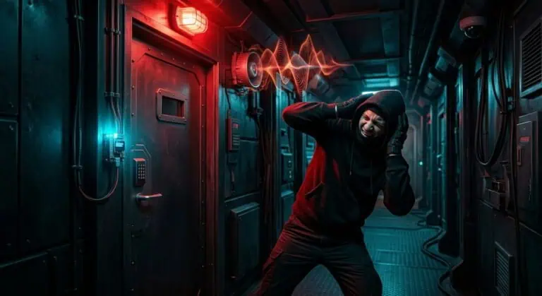
Author’s Note: This featured image is from a real photo clicked by me. AI tools and Canva were used solely to modify and enhance the image for sharpness and lighting clarity.
If you search online for a DIY Arduino laser tripwire security system, almost every tutorial shows the same basic setup: a single laser pointer aimed at a bare photoresistor (LDR).
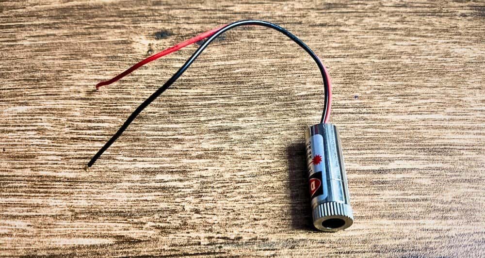
While a single beam works fine for a science fair table, it fails completely if you try to use a laser beam to catch people coming down a driveway or guard a real backyard perimeter. The first time a stray cat walks past, a bird flies through, or a dry leaf blows across the yard at 2:00 AM, the siren blasts a false alarm.
In this complete hardware guide, we will build a commercial-style Dual-Laser Security Alarm System powered by an Arduino Nano, a DS3231 Real-Time Clock (RTC), and a 0.96″ OLED display. By using twin laser beams and an automatic 9:00 PM to 6:00 AM night schedule, this system eliminates false triggers and runs hands-free.
Are Laser Security Systems Real? (Movies vs. Real Life)
Many people ask: Are laser security systems real, and do laser fields really exist in museums and homes?
In Hollywood heist movies, security grids are shown as glowing red webs zig-zagging across a room. In real physics, laser light is completely invisible in clean air unless there is heavy smoke, fog, or dust to scatter the beam.
However, real-world laser and twin-photobeam security systems are widely used across industrial perimeters, driveways, and high-security buildings:
- Single-Beam Tripwires (Toy/Basic DIY): Use one beam. If anything breaks the line—even a moth or falling twig—the alarm triggers.
- Commercial Dual-Laser / Twin-Photobeam Sensors: Industrial units (like outdoor twin-beam driveway sensors) project two parallel beams spaced a few inches apart. The alarm only triggers when both beams are blocked at the exact same moment, ignoring small animals, birds, and falling leaves.
Our Arduino Nano project replicates this exact commercial dual-beam architecture at a fraction of the cost.
Why This Dual-Laser Security System Is Useful
Whether you need a reliable laser security system for home driveways or a standout laser security alarm project for engineering, here is what makes this build genuinely useful:
- True Dual-Beam Logic (
D2&D3): The microcontroller monitors two separate laser receivers. Cutting Laser 1 alone or Laser 2 alone does nothing. Both beams must be interrupted simultaneously to trigger the siren. - Automatic Nighttime Arming (9:00 PM – 6:00 AM): Using a DS3231 RTC module, the system automatically arms itself at 9:00 PM (
21:00) and disarms at 6:00 AM (06:00). During daytime hours (6:00 AM to 9:00 PM), family members and delivery drivers can walk freely without setting off the alarm. - Instant Latching Alarm: If an intruder runs across your driveway and breaks the beams for just 100 milliseconds, the siren latches ON continuously until you press the physical RESET button (
D7). - 30-Second Obstacle Snooze Timer: If a car parks across the beam at night and you press RESET (
D7), the siren turns off immediately and starts a 30-second snooze timer. If the obstacle is still blocking both lasers after 30 seconds, the siren automatically re-triggers. - Single-Button Time Control & Live OLED Clock: The 0.96″ OLED displays the live current time (
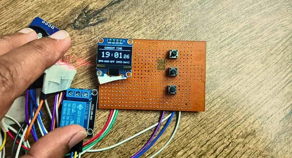
HH:MM:SS) and schedule status (9PM-6AM:ONorOFF). A short press on the MIDDLE button (D6) opens the time setting screen, and a 1.2-second long press saves the new time. - Dead-Battery Fail-Safe: If the RTC backup battery ever dies during a daytime power outage, the system detects the clock reset on boot and stays safely disarmed instead of triggering false alarms at noon.
Top Applications of a Laser Security Alarm
Where does a laser light security system outperform standard PIR motion cameras?
- Long Driveways & Entry Gates: Catch people or vehicles coming down a driveway across distances of 15 to 50+ meters where passive infrared (PIR) sensors cannot reach.
- Home Boundary Walls & Balconies: Create an invisible tripwire along compound walls and terrace ledges without picking up motion from neighbors or street traffic.
- Warehouses, Farms & Solar Perimeters: Protect straight fence lines, solar panel rows, and equipment sheds overnight without relying on Wi-Fi or cloud subscriptions.
Advantages and Disadvantages of a Laser Security System
If you are compiling a laser security system project report PDF, here is a quick technical comparison:
Advantages
- Zero False Triggers from Pets: Dual vertical beam spacing lets cats, dogs, and birds pass underneath or between beams without sounding the siren.
- Pinpoint Perimeter Line: Guards an exact straight line rather than a wide, blurry motion zone.
- 100% Offline & Subscription-Free: Operates independently on a 5V DC supply with backup RTC timekeeping.
Disadvantages & How Our Design Fixes Them
- Laser Diode Overheating: Cheap 5V laser diodes burn out if run continuously for 9 hours. Fix: We mount both laser transmitters inside aluminum laser heat sinks to keep them cool all night.
- Single-Beam Sensitivity: Standard laser projects trigger when leaves fall. Fix: Our dual-receiver AND-gate logic in software requires both beams to break at once.
Components Required (Bill of Materials)
To build this complete laser security system model, gather these components:
- Arduino Nano (
ATmega328P): 1 No. - DS3231 Real-Time Clock (RTC) Module + CR2032 Coin Battery: 1 Set
- 0.96-inch I2C OLED Display (128×64, SSD1306): 1 No.
- 5V Laser Transmitter Modules: 2 Nos.
- Aluminum Laser Heat Sinks: 2 Nos.
- 3-Pin Laser Receiver Sensor Modules: 2 Nos.
- 5V 1-Channel Relay Module (Active-HIGH): 1 No.
- Tactile Push Buttons (
UP,DOWN,MIDDLE,RESET): 4 Nos. - 5mm System ON Indicator LED + 470Ω Resistor: 1 Set
- 5V Regulated DC Power Supply (1A–2A) & Connecting Wires: 1 Set
Laser Security Alarm Circuit Diagram & Pinout Table
Follow the power distribution diagram and pin mapping table below to wire your modules to the Arduino Nano. Notice that both the DS3231 RTC and the 0.96″ OLED share the same I2C pins (SDA $\rightarrow$ A4 and SCL $\rightarrow$ A5).
Plaintext
                        +---> Arduino Nano [5V] Pin (Do NOT connect to VIN)
                        |---> 1-Channel Relay Module [VCC]
[ 5V Regulated ]  (+) --+---> Laser 1 & 2 Receivers & Transmitters [VCC]
[ Power Supply ]        +---> 0.96" OLED Display [VCC]

                  (-) ------> Common GND (Nano GND + All Modules GND + Buttons)
| Module / Component | Module Pin | Arduino Nano Pin | Connection & Signal Description |
| 5V DC Power Supply | +5V / -GND | 5V / GND | Connect regulated 5V directly to the 5V pin (bypass VIN). |
| DS3231 RTC Module | VCC / GND | 3V3 / GND | Connect VCC to 3V3 to protect the non-rechargeable CR2032 cell. |
| DS3231 & OLED (I2C) | SDA | A4 | Hardware I2C Data line (shared by RTC and OLED). |
| DS3231 & OLED (I2C) | SCL | A5 | Hardware I2C Clock line (shared by RTC and OLED). |
| 0.96″ OLED Display | VCC / GND | 5V / GND | Powered from the 5V rail. |
| Laser 1 Receiver | VCC / GND / OUT | 5V / GND / D2 | Digital input with internal pull-up (HIGH = Safe, LOW = Cut). |
| Laser 2 Receiver | VCC / GND / OUT | 5V / GND / D3 | Digital input with internal pull-up (HIGH = Safe, LOW = Cut). |
| Laser Transmitters (x2) | + / - | 5V / GND | Mounted in heat sinks and aimed at Receiver 1 & Receiver 2. |
| UP Button | Pin 1 / Pin 2 | D4 / GND | Increments hours/minutes in time menu (INPUT_PULLUP). |
| DOWN Button | Pin 1 / Pin 2 | D5 / GND | Decrements hours/minutes in time menu (INPUT_PULLUP). |
| MIDDLE Button | Pin 1 / Pin 2 | D6 / GND | Short Click = Time Menu / Next Field; 1.2s Hold = Save & Home. |
| RESET Button | Pin 1 / Pin 2 | D7 / GND | Silences active siren & starts 30-second obstacle snooze. |
| Siren Relay Module | VCC / GND / IN | 5V / GND / D8 | Active-HIGH output (HIGH = Relay ON, LOW = Relay OFF). |
| System ON LED | Anode (+) / Cathode (-) | D9 / GND | Wire D9 $\rightarrow$ 470Ω Resistor $\rightarrow$ LED +, and LED - $\rightarrow$ GND. |
3 Critical Hardware Notes Before You Power On
- Power via the
5VPin, NeverVIN: The Arduino Nano’sVINpin feeds into an onboard linear regulator that requires 7V–12V. Feeding 5V intoVINcauses a ~1.2V voltage drop, leaving your Nano and 5V relay starving at 3.8V. Always feed a regulated 5V DC adapter straight into the5Vpin. - Power the DS3231 RTC from
3V3: Most DS3231 breakout boards include a trickle-charge resistor intended for rechargeableLIR2032cells. Powering DS3231VCCfrom the Nano’s3V3pin ensures a standard CR2032 battery is never overcharged. - Avoid the
resp=0x00Upload Error: When uploading code over USB, temporarily unplug the external5Vwire from the Nano so the relay and lasers don’t draw excessive current from your PC’s USB port. In the Arduino IDE, select Tools $\rightarrow$ Processor $\rightarrow$ATmega328P (Old Bootloader).
Complete Arduino Nano Code
Install RTClib, Adafruit GFX, and Adafruit SSD1306 via the Arduino IDE Library Manager, then upload the complete firmware below:
Step-by-Step Workbench Testing Guide (No Lasers Required)
Because pins D2 and D3 are configured with internal pull-up resistors (INPUT_PULLUP), you can verify every feature on your desk using two jumper wires before mounting the lasers outdoors:
- Set the Clock to Night Mode: Click the MIDDLE button (
D6), use UP/DOWN (D4/D5) to set the clock to21:30, and hold MIDDLE for 1.2 seconds until the bottom of the OLED reads9PM-6AM:ON. - Normal Safe State: Leave
D2andD3open (unconnected). The internal pull-ups hold themHIGH, and the relay stays OFF. - Single-Beam Cut Test (Cat/Leaf Simulation): Connect a jumper wire from
D2toGNDwhile leavingD3open. The relay stays OFF. - Dual-Beam Cut Test (Intruder Simulation): Connect both
D2andD3toGND. The relay clicks ON immediately. - 30-Second Obstacle Snooze Test: Leave
D2andD3connected toGNDand tap the RESET button (D7toGND). The siren turns OFF, waits 30 seconds, and automatically clicks ON again.
Frequently Asked Questions (FAQ)
How does a dual-laser security alarm work compared to a single-beam setup?
A standard single-beam laser alarm triggers the moment anything breaks the line of light. This causes massive false alarms outdoors when leaves fall or cats walk by. A dual-laser system projects two parallel beams spaced a few inches apart vertically. The microcontroller’s logic requires both the top and bottom beams to be broken at the exact same millisecond to sound the siren, completely ignoring small animals and debris.
How do I make a laser security alarm system at home?
To build this custom system, you need five core stages:
Controller: Use an Arduino Nano to handle the logic and inputs.
Timing: Connect a DS3231 RTC module to I2C pins A4 and A5 so the system knows when it is night or day.
Sensors: Aim two 5V laser transmitters at two 3-pin laser receiver modules wired to digital pins D2 and D3.
Output: Wire a 5V Active-HIGH relay module to pin D8 to control your external siren.
Code: Upload a C++ script that reads both receivers and triggers the relay only if both beams cut simultaneously between 9:00 PM and 6:00 AM.
To make assembly completely error-free on your workbench, grab the exact project files directly from our LearnIoT.in resource library:
📥 [Download the Laser Security System Pin Diagram (PDF)]
💻 [Download the Complete Arduino C++ Source Code (.ino)]
Can I change the armed hours to something other than 9 PM to 6 AM?
Yes. The scheduling is handled in the Arduino firmware. To change the hours, find the isWithinArmedHours() function in the code. Change the line return (hr >= 21 || hr < 6); to match your preferred 24-hour start and end times. For example, to arm from 11:00 PM to 5:00 AM, change it to return (hr >= 23 || hr < 5);.
What happens to the security system during a power cut?
If the main 5V power goes out, the siren and lasers will shut down. However, the DS3231 RTC module has a dedicated CR2032 coin battery that keeps the internal clock running for years. When power returns, the Arduino Nano instantly reads the correct time from the RTC, checks if it is currently within the armed window, and resumes normal operation without you needing to reset the clock.
How do I silence the alarm if a car parks across my driveway at night?
If a permanent obstacle blocks both lasers during armed hours, simply press the physical RESET button wired to pin D7. The siren will turn off instantly and start a 30-second snooze timer. This gives you half a minute to move the vehicle. If the car is still blocking the beams after 30 seconds, the siren will automatically latch back on.
Why use a 3-pin laser receiver module instead of a cheap LDR sensor?
Light Dependent Resistors (LDRs) change resistance based on ambient light. If a car headlight, streetlamp, or porch light hits an LDR, it can trick the system into thinking the laser beam is still intact, allowing an intruder to walk right past. A 3-pin laser receiver module outputs a clean, reliable digital signal (HIGH or LOW) and is far less susceptible to ambient light interference.
Do I really need an aluminum heat sink for the 5V laser module?

Yes, for a permanent outdoor setup, it is highly recommended. Standard 5V laser diodes are not designed to be left on continuously for 9 hours straight (from 9:00 PM to 6:00 AM). Without a heavy-duty aluminum heat sink, the laser diode will quickly overheat and burn out within a few weeks. The fins safely dissipate the heat, ensuring your security system lasts for years. Additionally, the flat base allows you to mount it firmly to a wall, locking the alignment in place.
🛒 Where to buy: You can get the exact heavy-duty laser module with the built-in heat sink that I used for this project right here: Buy 5V Laser with Heat Sink on Robu.in